background image

10 

Safety Relay MINOS SD1E 

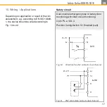
Application example 4: 

SD1E for dual channel safety door monitoring 
with manual start up to PL e / SIL 3. 

Fig. 6 

Dual channel safety door monitoring 

Note: 

Config-Switches are set as follows: 

S1

: Enabled / 

S2

: Manual 

(see chapter 7. “Function”) 

Note: 

Config-Switches are set as follows: 

S1

: Enabled / 

S2

: Automatic 

(see chapter 7. “Function”) 

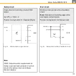
Application example 3: 

SD1E for two-channel monitoring of a non-
contact safety switch with short circuit moni-
toring and automatic start up to PL e / SIL 3. 

Fig. 5 

Dual channel safety door monitoring 


with non-contact safety switch


Summary of Contents for MINOS SD1E

Page 1: ...Operating Instructions Safety Relay MINOS SD1E MINOS SD1E...

Page 2: ...Am Gut Wolf 15 52070 Aachen Germany info zander aachen de www zander aachen de Version K11 E61 347 00 Engl Translation of the original document Subject to technical modifications no responsibility is...

Page 3: ...ng 12 10 Electrical connection 12 11 Commissioning 13 12 Checks and maintenance 14 13 Proof Test 15 14 Terminal assignment and LED displays 16 15 Wiring Applications 17 16 Time diagrams 24 17 Monitori...

Page 4: ...re every commissioning If there is a version change the use of the device in the overall application should be revalidated 1 Scope This document is valid for the following safety modules MINOS SD1E Or...

Page 5: ...esign Risk assessment and risk reduction IEC 62061 Safety of machinery Functional safety of safety related electrical electronic and programmable electronic control sys tems Additional requirements ma...

Page 6: ...061 IEC 61508 EN 50156 1 EN 746 2 IEC 61511 1 is used which will be brought into the safe state when the safety function is requested This means that the connected load is switched off as soon as a re...

Page 7: ...and S2 to configure the SD1E The following functions can be configured With the Config Switch S1 the function of the safety circuit at I1 I2 can be configured According to your application a cross ci...

Page 8: ...ided via the terminal S21 The start function can be set via the Config Switch S2 on the back of the device see chapter 12 Commissioning Safe relay contact 13 14 Considering the start behaviour the saf...

Page 9: ...th short circuit monitoring and monitored manual start up to PL e SIL 3 Fig 3 Two channel emergency stop monitoring with cross circuit monitoring Application example 2 SD1E for single channel emergenc...

Page 10: ...witches are set as follows S1 Enabled S2 Manual see chapter 7 Function Note Config Switches are set as follows S1 Enabled S2 Automatic see chapter 7 Function Application example 3 SD1E for two channel...

Page 11: ...utput Fig 7 Monitoring of an OSSD Output e g light curtain light grid with auto start Legend for all application examples E Stop Emergency stop button Start Start button KA KB Positively driven contac...

Page 12: ...d off Do not connect any external voltages to the output C1 The output C1 is short circuit proofed Overloading is not allowed and results in damage to the device see chapter 20 Technical data All indu...

Page 13: ...Power supply 5 Starting the device Switch on the power supply The LED UB starts lighting immediately If the Automatic start behaviour is set the safe relay contact will close immediately with a closed...

Page 14: ...ystem is working properly in particular Every time after initial commissioning Every time after replacing a component After a long downtime After every fault Regardless of this the safe functioning of...

Page 15: ...on by opening the safety circuit Check that the relay contact 13 14 opened by activation of the safety function Close the safety circuit and start the device again Check that the relay contact 13 14 c...

Page 16: ...C 24 V A2 Power Supply 0 V S21 Control line start I1 Control line safety circuit 1 I2 Control line safety circuit 2 13 Safe Relay Contact 14 Safe Relay Contact C1 Auxilliary Output SD1E Variant label...

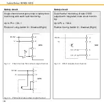
Page 17: ...ing to EN ISO 13849 1 the device should be wired according to Fig 10 to 22 Safety circuit Dual channel emergency stop or safety door monitoring with short circuit monitoring Up to PL e SIL 3 Position...

Page 18: ...c SIL 1 Position Config Switch S1 Disabled Right Fig 12 Potential free NC contact single channel Fig 13 PNP solid state output single channel Safety circuit Dual channel monitoring of safe OSSD output...

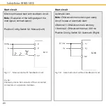
Page 19: ...ngle channel Start circuit Monitored manual start without feedback circuit Note Evaluation of the falling edge of the start signal contact opens Position Config Switch S2 Manual Left Fig 16 Manual sta...

Page 20: ...back circuit Note Evaluation of the falling edge of the start signal contact opens Position Config Switch S2 Manual Left Start circuit Automatic start Note Difference time monitoring at safety circuit...

Page 21: ...nce time is arbitrary I1 before I2 Difference time max 300 ms Position Config Switch S2 Automatic Right Fig 19 Automatic start with feedback circuit KA KB Positively driven NC contacts of the connecte...

Page 22: ...ession Note Fault exclusion of a cross circuit should be carried out in the safety contact 13 14 e g in accordance with EN ISO 13849 2 table D4 D5 Cables within an electrical installation space in acc...

Page 23: ...23 Safety Relay MINOS SD1E EN...

Page 24: ...24 Safety Relay MINOS SD1E 16 Timing diagrams SD1E with automatic start Fig 23 Timing diagram SD1E with automatic start tE Switch on delay typ 10 ms tA Switch off delay typ 10 ms...

Page 25: ...25 Safety Relay MINOS SD1E EN SD1E with monitored manual start Fig 24 Timing diagram SD1E with monitored manual start tE Switch on delay typ 10 ms tA Switch off delay typ 10 ms...

Page 26: ...ion of the Config Switch S1 see chapter 7 Function Signal to the safety circuit I1 is missing Check the sensor at the input I1 Has an emergency stop been triggered or are safety doors open Check if th...

Page 27: ...the synchronisation time between I1 and I2 If I1 is present before I2 then the maximum time between the two signals should not exceed 300 ms Monitored manual start Check the wiring of the reset circui...

Page 28: ...t the following intervals Once a month for applications up to PL e with Cat 3 respectively Cat 4 or SIL 3 with HFT 1 Once a year for applications up to PL d with Cat 3 or SIL 2 with HFT 1 The followin...

Page 29: ...15 5 A Max 10 000 Switching Cycles Year DC 13 4 A Max 15 000 Switching Cycles Year Max duration of use Years 20 Category 4 PL e PFHd 1 h 1 2E 08 Conditions AC 15 5 A Max 10 000 Switching Cycles Year...

Page 30: ...igh level max 21 mA Galvanic isolation no Low level 0 V to 5 V High level 21 6 V to 26 4 V Pulse suppression Signal to 0V Dark Test Pulse to 0 V Light Test Pulse to UB Max 5 ms Max 1 ms Note It must b...

Page 31: ...cc to EN 50156 1 chapter 10 5 5 3 4 Mech Service life approx 1x10⁷ cycles Contact material AgSnO2 Auxiliary output C1 Structure PNP output single channel Maximum switching capacity 100 mA Galvanic iso...

Page 32: ...ation voltage 50 V For SELV PELV circuit 250 V Between relay circuit and SELV PELV circuit Rated surge voltage strength 800 V Basic insulation for SELV PELV circuit 6 kV Safe insulation reinforced ins...

Page 33: ...mum permissible current at safe relay contact 13 14 depending at on the ambient tempera ture Fig 25 Derating curve UB DC 24 V and 0 mm clearance to adjacent devices with same load UB DC 26 4 V and 0 m...

Page 34: ...Order No Order No Type Application 472841 SD1E Emergency stop relay for the connection of safety sensors e g light curtains light grids safety RFID switches emergency stop buttons safety rope switches...

Page 35: ...Relay MINOS SD1E EN 23 Service For service requirements contact H Zander GmbH Co KG Am Gut Wolf 15 52070 Aachen Germany Service line 49 241 910 501 0 E mail info zander aachen de Internet www zander...

Page 36: ...36 Safety Relay MINOS SD1E 24 Declaration of Conformity...

Page 37: ...37 Safety Relay MINOS SD1E EN...

Page 38: ...uments listed in this manual Standard Document Edition EN ISO 13849 1 2016 06 EN ISO 13849 2 2013 02 IEC 62061 2016 05 IEC 61508 2011 02 IEC 61511 2005 05 EN 50156 1 2016 03 EN 746 2 2011 02 EN ISO 12...

Page 39: ...39 Safety Relay MINOS SD1E EN...

Page 40: ...40 Safety Relay MINOS SD1E...

Reviews: