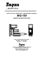
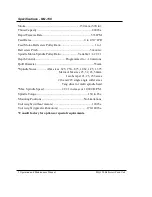


7 Operation and Maintenance Manual
MQ-150 Ballscrew Feed Unit
Electrical
The standard Zagar control packages are simple to connect and come as complete
enclosures ready for mounting and connection. We provide three basic packages for
all Ball screw Feed Units. All include the same AC brushless servo motor on the feed
(ball screw) axis. The distinction between the three packages is the spindle motor.
The first package is the simplest containing a fixed speed AC three phase premium
efficiency motor. The second package utilizes an inverter for variable speed
operation. The speed is controlled with the servo control and is fully programmable.
The third and most sophisticated package uses the same type of AC brushless servo
motor on the spindle axis that is used on the feed axis. It provides the capability for
positioning of the spindle in rotation for synchronized, 2 axis motion as is used in
rigid tapping operations. This package has a two axis, programmable servo control
whereas the other two packages have a one axis servo control for the feed axis only.
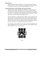
These controls only require connection to the unit and connection to power. Most of
the connections to the units are quick connect, military style. A standard program is
provided with all servo controls. No additional programming or programming
experience is required to use these controls. The operator interface provides an easy
to use, prompt type system for data entry and operation.
Please note that if you have chosen to provide your own controls, all engineering,
mounting and connection requirements are the responsibility of the customer. Zagar
Incorporated assumes no responsibility for operation, control or programming of the
units when a control other than a Zagar Incorporated Servo Control Package is used.
General Connection Instructions
- Refer to any manuals, special instructions and
diagrams included with your specific unit for additional electrical information on the
electronics drive and control package. The basic needs for electrical connection with
a Zagar Servo Control Package are given below. Where necessary, they are described
in greater detail following this section.
1.
Mount cabinet within 10 feet of unit using four mounting tabs attached to control
enclosure.
2.
Run power, feedback and proximity sensor cables (included and attached) from
control to unit and attach to motors and proximity sensors, see electrical
drawings.
3.
If the spindle motor is being used with a variable speed drive select a proper
length wire of no smaller than 12 gauge and connect the three phases of the
spindle motor, see electrical prints, to terminal blocks inside the Zagar Servo
Control enclosure.


