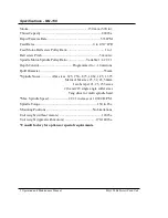

6 Operation and Maintenance Manual
MQ-150 Ballscrew Feed Unit
Setup Instructions
Mechanical - Unpacking and installation
The MQ-150 unit has few setup requirements. The following instructions provide the
necessary information to prepare the unit for operation. If you are providing your own
controls, additional work will be required and is described at the end of this section.
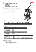
Refer to diagrams for dimensions and feature locations. A quick reference sheet is included
in the appendix for general installation and connection requirements.
Unpack the unit from the shipping container and inspect the unit. Report any damage to
Zagar Incorporated immediately.
Make certain when lifting the unit from the shipping container, a proper lifting device is used
and is attached securely to the unit. A safe lifting location is the gap between the spindle
motor mount and the unit it is attached to. This provides a closed opening from which the
strap cannot slip.
* DO NOT lift the unit from the motor eyebolt. This is intended for lifting of the
motor only.
* DO NOT lift the unit by the quill or spindle. Damage to the unit may result.
The unit is provided with one of two types of mounting devices. They are either a base
mount or a barrel mount. The base mount is an integral component which comes attached to
the standard unit. The barrel mount is an optional mounting device which is specified at the
time of order and is connected to the front barrel of the unit. Each of the mounting devices
share the same features of four holes for bolting the unit to a mounting surface and a keyway
for locating and orientating the unit.
The base mount has holes are 9mm dia. thru for use with either M8 socket head cap screws
or 5/16 socket head cap screws. The mounting hole has a 14.3mm dia. spot face which
results in an overall base flange thickness height of approximately 16mm. This dimension
can be used in choosing the screw length to be used for mounting
. The center height of the
unit with this mount is shown on the diagram in the appendix.
Secure and align the unit to the mounting surface using the four holes and keyway on the
mount.
The unit is self contained with few external adjustments required and should not need any
other mechanical installation requirements.
If you are providing your own controls and motors, you will have already had to arrange for
the proper feed and spindle motor mounting brackets. If the motors are not mounted at Zagar
Incorporated, it will be necessary to bolt each motor to the corresponding motor mount or
mounting plate and secure the included pulleys (may or may not have bushings). And
properly tension the belts for proper operation. Belts must be secure without free slack but
cannot be overtight or excessive noise, reduced belt life and premature failure of the spindle
motor bearings may result.
Feel free to contact the factory for any other mounting or installation questions.