Z Microsystems ZX1 User Manual Download Page 5

Issued: 01/21/10 REV 50 

Doc# 27-0042UM 

8

9

Issued: 01/21/10 REV 50 

Doc# 27-0042UM 

INSTALLING A ZX1 STATION IN A RACK

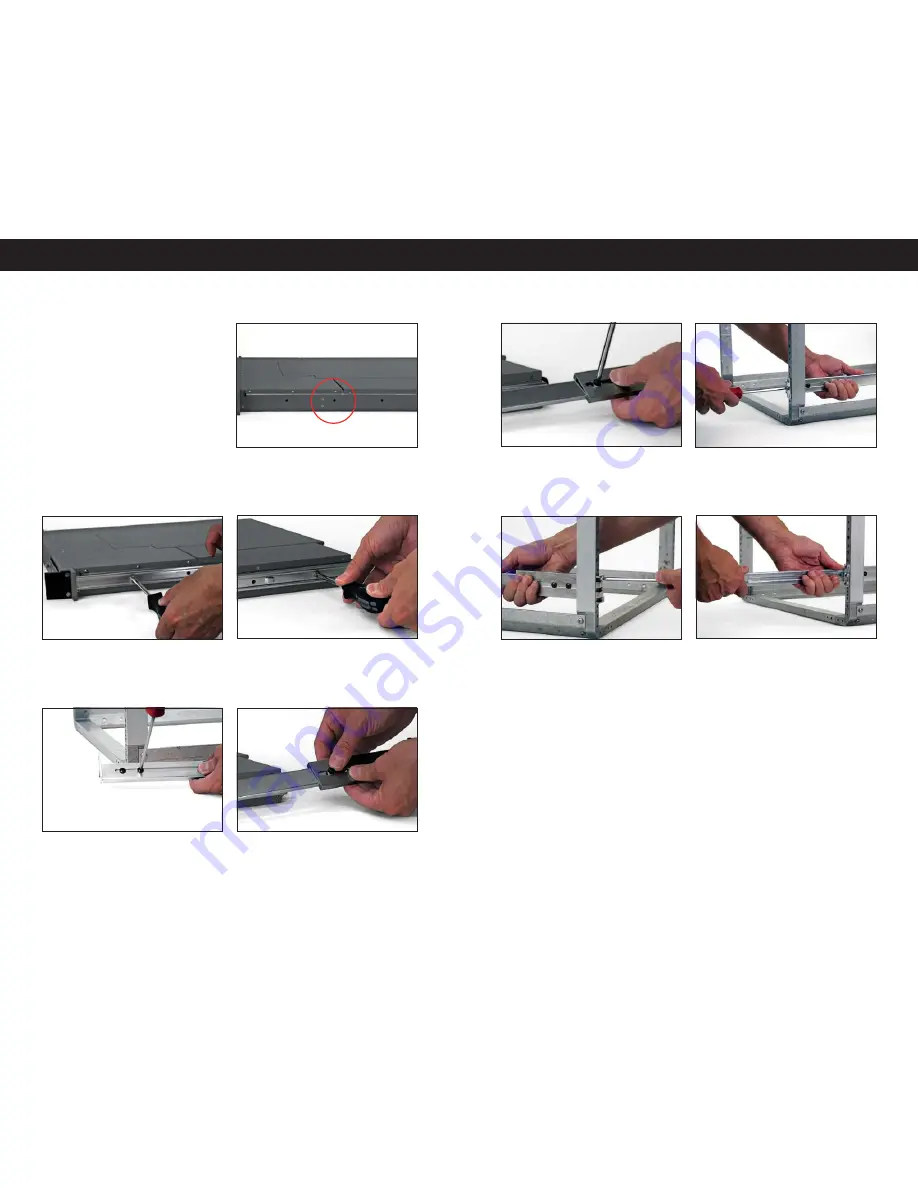
1. The sides of your Z X1 Station will
be pre-tapped for installing the slide rail 
components.

3. Fasten the rear side of the stationary 
rail to the ZX1 unit and fasten all other
assembly screws in the middle of the 
component.

5. Place the metal slide extension over 
the sliding rail arm component. Align the 
elliptical holes at the length to fi t your rack. 
Fasten with assembly screws and washers.

4. Fasten the front face bracket over the 
sliding rail arm component with screws 
and washers using a Philips screwdriver. 
Align the elliptical holes to fi t your rack. 

6. Using a Philips screwdriver, tighten the 
screws to clamp the two pieces together 
for both the front and rear brackets.

2. Attach the stationary rail to the side of 
the ZX1 unit using a Philips screwdriver 
and assembly screws no longer than .18”. 
Repeat on other side.

INSTALLATION

NOTE: 

Slide extensions will be 

required for rack depths greater 
than 26 inches. If slide extensions 
were not part of your order, 
please contact a Z Micro sales 
representative for additional 
assistance. For 24 to 26 inch 
depth racks, the slides can be 
directly attached to the rack.

7. Position the front of the assembled 
slide rail c omponent onto the rac k in
the desired location. Attach with screws 
using a Philips sc rewdr iver.

9. Pull both slide arms out and for ward 
of the rack.

8. At the rear of the rack, attach the other 
side of the slide rail component at a level 
position. 

INSTALLATION

INSTALLING ZX1 STATION IN A RACK

Summary of Contents for ZX1

Page 1: ...ZX1...

Page 2: ...CAUTION RISK OF ELECTRIC SHOCK DO NOT OPEN CAUTION TO REDUCE THE RISK OF ELECTRIC SHOCK DO NOT REMOVE COVER OR BACK OF UNIT NO USER SERVICEABLE PARTS INSIDE REFER SERVICING TO QUALIFIED PERSONNEL This...

Page 3: ...eers are experts in the design of systems that reduce the risk cost and failure caused by harsh environmental conditions Designed to exceed MIL STD 167 for vibration and MIL STD 461 for EMI ZX1 Statio...

Page 4: ...s Remember to save the unit s original shipping materials It may be necessary to move the unit at a later date SHIPMENT CONTENTS INSTALLATION NOTE For the fastest and easiest installation of the ZX1 S...

Page 5: ...hilips screwdriver tighten the screws to clamp the two pieces together for both the front and rear brackets 2 Attach the stationary rail to the side of the ZX1 unit using a Philips screwdriver and ass...

Page 6: ...he lock button s flange on the stationary rail use your thumb to push down the flange in order to bypass and continue 9 The ZX1 unit should stop just short of the slide rail s front flange 1 Engage th...

Page 7: ...pulling t he locking latches towards the Memory DIMM 2 Use your fingers to push the locking latches away from the existing Memory DIMM Gently remove the Memory DIMM from its slot OPERATIONS RE INSTAL...

Page 8: ...ZX1 station OPERATIONS NOTE If one of the Power Supply modules is removed then the system will still operate with the one remaining power supply A failed power supply will be identified by an audible...

Page 9: ...Face Plate Cover is an option available only to certain models INSTALLING THE LOCKABLE FACE PLATE COVER 1 The face plate cover has small flanges on the left side that perfectly fit within correspondin...

Page 10: ...y indicate hard drive items that require attention If such is the case please refer to the Troubleshooting in the Appendix POWERING UP THE ZX1 STATION OPERATIONS 1 Slide the locking catch towards the...

Page 11: ...2 Green system is ON 3 OFF system is not connected to an AC power source OT Over Temp LED 1 OFF System temperature is normal 2 Blinking Red Light This is a warning that the system temperature is getti...

Page 12: ...rgent and wipe the surface gently MAINTAINING THE ZX1 MAINTENANCE 1 Remove the unit face plate by releasing the screw on the left side of the unit Repeat the procedure on the right side 2 Once the uni...

Page 13: ...operly connected to the power supply 2 Check that power to the system is good 3 Check that power to the power supply is engaged 4 If neither of these is the cause contact Z Microsystems Customer Servi...

Page 14: ...bration MIL STD 167 Up to 25 Hz Extended vibration environments are achievable with Solid State Drives Above 25 Hhz throughput will degrade with spinning HDDs Operating Shock 30g s Saw tooth 11ms EMI...

Page 15: ...ship date on your invoice is your product ship date unless Z Microsystems informs you otherwise During the warranty period Z Microsystems will provide warranty service under the type of warranty purch...

Page 16: ...ersion number 6 Operating System and version number NOTE If possible stay by the computer The Z Microsystems Technical Support Representative may wish to go through the problem over the telephone NOTE...

Page 17: ...Z Microsystems Inc 9820 Summers Ridge Road San Diego CA 92121 Phone 858 831 7000 Fax 858 831 7001 Website www zmicro com Copyright 2009 Z Microsystems Inc All Rights Reserved...

Reviews: