background image

Preface

Please read this document carefully in order to understand the ZOLAR™ Vega 30C (hereinafter 

referred to as Product) and use it reasonably. Refer to the official website (www.z-cam.com/zolar) 

for the latest version of this document and updated product information.
Please contact Shenzhen ImagineVision Technology Limited (hereinafter referred to as 

ImagineVision) or its authorized distributor/resellers, in case of any product queries about installa-

tion or operation.

Safety Guideline

Please read and follow this Safety Guideline and all the terms associated to this Product carefully, to 

know your legal rights, responsibilities, and safety instructions, otherwise, it may result in product 

damages, safety accidents and personal injuries. By using this Product, you hereby signify that you 

have read, understood, acknowledged and accepted this Safety Guideline and all the terms and 

conditions associated with this Product, and assume responsibility for any behaviors or consequen-

ces. You undertake to use this Product on normal and reasonable purpose, and agree to this Guide-

line and all the terms and conditions associated with this Product, as added, reduced, amended, 

modified made by ImagineVision from time to time.
ImagineVision provides no expressed or implied guarantee in relation to this Product, assumes no 

loss or legal responsibility raised from misuse of this Product contrary to this Safety Guideline and 

the terms associated to this Product, accepts no indirect, consequent, punitive, occasional, special, 

criminal-punitive loss or legal responsibility. Under any circumstances, the total liability of 

ImagineVision shall NOT exceed the price paid by you to ImagineVision for the product.

Safety Warning

This Product is not intended for use by persons under the age of 18. Keep out of reach of children.

1 . Keep children away when operating the product.

2. Do not stare at the light source as it may cause permanent eye damage.

3.


Wear gloves before touching heated surfaces of the product to prevent burns.

4.


Wear gloves when touching sharp edges and corners of the product to prevent cuts.

5. Do not block or cover the vents of the product.

6. Product is not waterproof and not dust proof. Prevent water and dust from entering into the pro-


duct which may cause damages.

7.  Position the power cables so that it will not be tripped over, or accidentally pulled out causing the 


product to shut down.

8.


If an extension power cable is required, the minimum amperage rating should not be less than 


that of the product’ s own power cable.

9. 


When using the device with AC DC Power Adapter, connect it to a grounded power outlet.

10.Do not place the product near any flammable and/or volatile liquid to prevent potential damages.

2

Disclaimer

All product features and technical specifications stated are subject to the sole interpretation and 

explanation of Shenzhen ImagineVision Technology Limited, and subject to change without notice.

Version 1.0.0

Copyright © 2022 Shenzhen ImagineVision Technology Ltd. All Rights Reserved

Summary of Contents for ZOLAR Vega 30C

Page 1: ...TM Vega 30C User Manual...

Page 2: ...ideline and the terms associated to this Product accepts no indirect consequent punitive occasional special criminal punitive loss or legal responsibility Under any circumstances the total liability o...

Page 3: ...nstallation Power Supply Start Up Menu Operation Remote Controller Connection Mobile App Bluetooth Connection Wi Fi Connection Firmware Upgarde Operation Guide CCT Mode HSI Mode xy coordinate Mode Gel...

Page 4: ...ox Accessory Kit 32x32 Optional Accessories Product Specifications Photometric data Warranty Policy Warranty Scope Warranty Period Warranty Arrangement Limited Warranty FCC Compliance Statement RF War...

Page 5: ...onsistent LED performance issues In addition our revolutionary solution allows a mixture of ZOLAR light series to be used simultaneously without any visible color deviation color matching mode will be...

Page 6: ...Vent Holes 8 Quick Release Button 9 V Mount Plate 10 DMX Output 11 DMX Input 12 Ethernet Port 13 Bottom Handle 14 Vent Holes 15 Top Handle 16 Main Unit Controller 17 Power Switch 18 Battery Input 19...

Page 7: ...tor 26 Rotary Encoder 27 Mode Button 28 Menu Button 29 Favorite Button 30 F3 Button 31 F2 Button 32 F1 Button 16 Main Unit Controller Main Unit Controller Copyright 2022 Shenzhen ImagineVision Technol...

Page 8: ...ease Button 37 V Mount Clip 38 AC Input 39 AC Loop Out 40 Battery Power Output 41 Power Switch 42 DC Power Output Power Supply Unit Front Left Top Bottom 33 34 35 36 37 38 39 40 41 42 Copyright 2022 S...

Page 9: ...tton 49 Right Button 50 F3 Button 51 Menu Button 52 Favorite Button 53 Power Switch 54 Remote Controller Port 43 44 45 46 47 48 49 50 51 52 54 Front Bottom Right 9 44 Remote Controller 53 Version 1 0...

Page 10: ...mote Controller 1 pc ZOLAR Stylist W Side A ZOLAR Stylist W 32x32 Version 1 0 0 Main Unit 1 pc 55 AC Power Cable CN 1 pc 56 DC Power Cable 3 Pin 1 pc 57 Battery Power Cable 4 Pin 1 pc Power Supply Uni...

Page 11: ...n is adjustable 360 2 Mount the Main Unit onto light stand head mount through Spigot 06 rotate Hand Knob Swivel Screw Clamp 05 clockwise until it is tightened 3 Repeat above step 1 to adjust the incli...

Page 12: ...er outlet 110 240 V 50 60 Hz 4 To disconnect make sure the power switch is in OFF position unplug AC Power Cable 55 from power outlet press and hold the safety lock of AC Power Cable 55 to pull it out...

Page 13: ...t 40 of the PSU the other end to the Battery Input 18 of the Main Unit 4 To unmount the battery press and hold the Quick Release Button 36 of the PSU and lift the battery upward Press and hold the saf...

Page 14: ...confirm selection Press Menu Button 28 to return to the upper level menu Remote Controller Connection 1 Connect the Remote Controller cable 58 to the Remote Controller Port 20 of the Main Unit the oth...

Page 15: ...icon on top of the home screen and select the corresponding Main Unit then click to confirm f Press Menu Button 28 to return to upper level menu g ZOLAR Mobile App is now ready to control the Main Uni...

Page 16: ...er menu b Rotate Rotary Encoder 26 to select Wi Fi press once to enter WiFi menu c Rotate Rotary Encoder 26 to select Disconnect press and select Yes then press again to confirm disconnection Firmware...

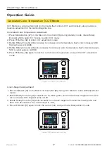
Page 17: ...Magenta Adjustment Graphic CCT Adjustment Interface 2022 17 Version 1 0 0 G M Correlated Color Temperature Adjustment CCT Mode is a simple white light control mode that controls CCT and Intensity als...

Page 18: ...26 clockwise to increase intensity Each click increases 0 1 Highest value is 100 3 Rotate Rotary Encoder 26 anti clockwise to decrease intensity Each click decreases 0 1 Lowest value is 0 4 Press F3 B...

Page 19: ...ise to decrease hue value Each click decreases 0 1 Lowest value is 0 0 5 Press F1 Button 32 again to lock the current hue and quit the Hue adjustment mode Graphic Hue Adjustment Interface 1 Press F2 B...

Page 20: ...ue Each click increases 0 001 4 Rotate Rotary Encoder 26 anti clockwise to decrease x value Each click decreases 0 001 5 Press F1 Button 32 again to lock the current x Coordinate and quit the x Coordi...

Page 21: ...the Category options which are Color Correction CalColor Storaro Selection and CineLux 5 Press F1 Button 32 again to switch to the L option 6 Press F3 Button 30 to switch the Category options which ar...

Page 22: ...ect Source Matching Mode press to enter Source Matching menu 2 In the Source Matching menu press Rotary Encoder 26 to enter the Light Source Selection menu 3 Press F3 Button 30 to switch the light sou...

Page 23: ...r to delete all 2022 23 Version 1 0 0 RGBW Mode RGBW Adjustment RGBW Mode is used to adjust the ratio of the four channels of red green blue and white The Intensity can be adjusted as usual 1 Press Mo...

Page 24: ...of light effects Candle Cloud Passing Club Lights Cop Explosion Fire Fireworks Flicker Lightning Paparazzi Party Pulsing Strobe Television Welding Process Fade In Out 2022 24 Version 1 0 0 Cloud Passi...

Page 25: ...otate Rotary Encoder 26 to select the desired intensity press F3 Button 30 to lock the intensity and quit intensity adjustment mode 3 Settings of Effect a Press F1 button 32 in Effect menu to enter Se...

Page 26: ...ve if you want to use high precision at high brightness Linear The intensity change is proportional to the value adjusted by the Rotary Encoder 26 S curve The dimming precision is high at both lower a...

Page 27: ...slave will be successfully networked within 5 seconds the top area of the Controller LCD Screen 24 of the master will display a magenta connection icon and the number of connected slaves and the indic...

Page 28: ...he slaves of the same group ID will be automatically synchronized to the same settings b After synchronization each slave can be set individually as required without affecting the original settings of...

Page 29: ...ncoder 26 select Group ID press to enter the ID setting menu press to change the group ID rotate Rotary Encoder 26 to select the same group ID between 0 and 15 as the master and then press again to co...

Page 30: ...p ID 2 14 Group ID 15 Master Master Master Slave Slave More Slaves Slave Slave More Slaves Slave Slave More Slaves Graphic ZolarLink Group Management Copyright 2022 Shenzhen ImagineVision Technology L...

Page 31: ...rn the M I S Selector 16 to select the I position and turn on the power The indicator 21 turns a steady green indicating that the main unit has returned to the idle state 7 Exception Handling If the s...

Page 32: ...6 press the Menu Button 28 to enter the menu list 2 Rotate Rotary Encoder 26 select Settings and press to enter the Settings menu 3 Rotate Rotary Encoder 26 select LCD Brightness and press it to enter...

Page 33: ...exit the Fan menu 1 On the standby interface of the Main Unit Controller 16 press the Menu Button 28 to enter the menu list 2 Rotate Rotary Encoder 26 select Settings and press to enter the Settings m...

Page 34: ...hase on your own The standard package includes a ZOLAR Stylist W 32x32 it is recommended to install and use together for best results ZOLAR Stylist W Side A ZOLAR Stylist W 32x32 Stand package ZOLAR S...

Page 35: ...tly to the locked position Graphic Insert ZOLAR Stylist Take Out ZOLAR Stylist 32x32 1 Gently push the slide latch 23 inwards to the unlocked position 2 Flip the top frame up to reveal the 3x ZOLAR St...

Page 36: ...fessional light control effects ZOLAR Barndoor 32x32 Version 1 0 0 1 Gently push the slide latch 23 inwards to the unlocked position 2 Flip the top frame up to reveal the 3x ZOLAR Stylist Slots 02 3 S...

Page 37: ...me push the slide latch 23 lightly to the locked position 1 Cut the Velcro to the specified length and paste it as shown 2 Tear off the velcro sticker on the Barndoor 3 Connect the Blackout Cloth to t...

Page 38: ...and the range of illumination create a light source effect with a prominent center and a soft transition between light and shade at the edges Mount the ZOLAR SoftBox 32x32 1 Unfold the ZOLAR SoftBox...

Page 39: ...Cloth from the ZOLAR SoftBox Holder along one corner 2 Unfold the ZOLAR SoftGrid and attach each side of the Velcro strap to the front side of the ZOLAR SoftBox and make the whole fixed firmly Graphic...

Page 40: ...Pin Baby 5 8 Junior 1 1 8 Combo Pin 28 mm Spigot Junior Pin Power Input Power Connection Battery Input PSU Power Consumption 48 V 5 2A DC Male 3 Pin XLR 15A Pin 1 Negative Pin 2 Positive Dual V Mount...

Page 41: ...xWxL Mounting Certifications PSU250 100 240V 50 60 Hz 100 240V 50 60 Hz 48V 5 2A DC Dual V Mount 12 8 16 8V 180Wh min 26 33 6V 1 54 kg 105 x 100 x 295 mm V Mount Plate CE FCC UKCA Disclaimer All measu...

Page 42: ...2 499 lx 232 Fc 90 w ZOLAR Stylist W 3 m 9 8ft CCT 3 200K 350 lx 33 Fc 591 lx 55 Fc 838 lx 78 Fc 881 lx 82 Fc 838 lx 78 Fc 591 lx 55 Fc 350 lx 33 Fc 4 000K 347 lx 32 Fc 587 lx 55 Fc 832 lx 77 Fc 876...

Page 43: ...uct is found defective either due to material or workmanship issues by ImagineVision or its designated approved service partners within the warranty period ImagineVision or its designated approved ser...

Page 44: ...his equipment generates uses and can radiate radio frequency energy and if not installed and used in accordance with the instructions may cause harmful interference to radio communications However the...

Page 45: ...n of the User Manual on the ZOLAR official website https www zcam com zolar vega 30c If you have any questions or suggestions about the User Manual please contact us via the following email marketing...

Reviews: