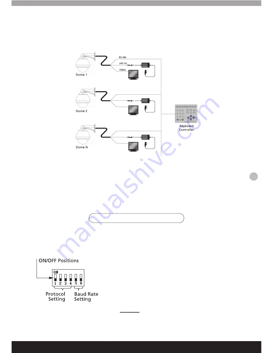
When connecting multiple speed domes, the user can expand the system with additional devices such as a
capture device, video matrix, DVR or an alarm box.
AC24V:
The camera’s power supply, will convert 110V/60HZ or 220V/50HZ input to a AC 24V output.
RS-485 Bus:
The RS485 signal output from the controller connects to the RS485 wires from each of the cameras,
allowing one controller to control many speed domes.
Video:
The video signal from each speed dome can directly output to video equipment such as monitor or video
matrix. !!Take care to match up the impedance!!
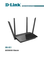
Before installation and use, set the communication protocol and transmission speed (baud rate), as shown
below.
1. Setting protocol and baud rate of the camera
Multiple Speed Domes
Fig 1.9
When setting the communication protocol of the camera, the
first 4 characters on the dip switch are used to set default
serial transmission rate of the protocol. If the default baud rate
of the protocol does not match with baud rate of host, reset
the default baud rate of the protocol consistent with default
baud rate of host (See table on page 10). The table lists
protocols that are suitable for this camera. Normal operations
of these protocols are compatible with domestic and foreign
main systems.
Attention:
The protocol and baud rate of the camera should
comply with those of controller, which needs to be restarted
after making changes to the settings. (Page 15)
Camera- Communication Settings
9


