background image

FORM 160.52-M2

YORK INTERNATIONAL

9

6. Using ENTRY keys, press “1” if the STANDBY

LUBRICATION feature, as described below, is
desired. Otherwise, press “0” .

7. Press ENTER key.

8. If FIXED SPEED oil pump application was se-

lected, by entering “0” in step 2 above, press PRO-
GRAM key to exit. Otherwise, press ADVANCE
DAY/SCROLL key.


OIL PRS CTRL PERIOD = __ x 0.3 SECONDS

is displayed.

9. Using ENTRY keys, enter desired value “1”

through “9”. Recommended value “3” will pro-
vide correct operation in most applications. If the
CANCEL key is pressed, default value “3” is dis-
played.

10. Press ENTER key.

11. Press ADVANCE DAY/SCROLL key.

    OIL PRESSURE SETPOINT = XXPSID

is displayed.

12. Using ENTRY keys, enter desired value between

“20” and “45” PSID. Recommended value “35”
will provide correct operation in most applications.
If CANCEL key is pressed, default value “35” is
displayed.

13. Press ENTER key.

14. Press ADVANCE DAY/SCROLL key.

    OIL PUMP VSD FREQUENCY = XX Hz

is displayed.

15. Using ENTRY keys, enter desired value between

“25” and “ 60” Hz. If CANCEL key is pressed,
default value “25” is displayed.

16. Press ENTER key.

17. Press PROGRAM key to exit.
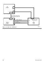
MICRO BOARD CHANGES

The VSOP drive’s PWM speed command input is gener-
ated on the Micro Board and is fed to the VSOP drive via
J10-2. J10-2 is not present on Micro Board part number
031-01065-001. The Micro Board has been revised to
include these circuits and the part number has been
changed to 031-01065-002. Micro Board part number
031-01065-002 is required on all VSOP drive applications.

STANDBY LUBRICATION

To maintain oil seal integrity while the chiller is shut
down, the oil pump is turned on for 2 minutes every 24
hours, if the chiller has not run in the past 24 hours.
While the pump is running,


 STANDBY LUBE IN PROCESS - X.X MIN LEFT

is displayed. If a VSOP drive is installed, the operating
oil pressure will be the programmed oil pressure setpoint,
programmed by the Service Technician.

To prevent oil pump damage due to low oil level, if at
least 15 PSID of oil pressure is not achieved within 30
seconds of starting the oil pump, the cycle is terminated
and


STANDBY LUBE LOCKOUT- CHECK OIL LEVEL

is displayed when the STATUS key is pressed. No more
standby lubrication cycles will be performed until the
WARNING RESET key is pressed in SERVICE mode,
at which point another cycle will be attempted. Starting
the chiller also resets this STANDBY LUBE LOCK-
OUT.

Standby lubrication cycles will not be performed if either
oil pressure transducer is out of range (HOP < 6.8 PSIG;
LOP < 0 PSIG). No message will appear to indicate that
the lubrication cycle will not be performed. The verifica-
tion of correct pressure assures that standby lubrication
cycles will not be performed during maintenance of the
chiller or until the chiller has been charged with refriger-
ant and chiller commissioning has been completed.

These standby lubrication cycles are enabled or disabled
by the Service Technician using the VSOP drive selec-
tion procedure described above. It is recommended that
the standby lubrication be enabled on chillers that re-
main shut down for periods of 24 hours or greater.

Summary of Contents for YK

Page 1: ...MODEL YK MODEL D E CENTRIFUGAL LIQUID CHILLERS SERVICE INSTRUCTIONS VARIABLE SPEED OIL PUMP DRIVE Supersedes Nothing Form 160 52 M2 899 00130VIP...

Page 2: ...SOP DRIVE 11 Oil Pump Drive Status LED 11 VSOP Drive Okay Relay 11 Auto Resettable Shutdowns 11 Non Auto Resettable Shutdowns 12 TROUBLESHOOTING GUIDE 13 DRIVE REPLACEMENT INSTRUCTIONS 14 MOST FREQUEN...

Page 3: ...r the standard chiller Version C 02T 16 Part Number 031 01431 003 will be avail able for Remote Chiller Communications applications The Micro Board will change from a 031 01065 001 to a 031 01065 002...

Page 4: ...Z PRS XX XPSID MICROCOMPUTER CONTROL CENTER OPERATION The Microcomputer Control Center maintains desired system oil pressure by controlling the speed of the oil pump The speed at which the oil pump ru...

Page 5: ...LOSE REFRIGERANT LEVEL OPEN OIL PUMP VSD SPEED CONTROL 3R 1M 2 1 HTR J10 1 2 3 J2 2 J2 1 J2 3 REFRIGERANT LEVEL CONTROL BOARD OIL PUMP VARIABLE SPEED DRIVE PWM RUN V 3R 1 J4 2 J4 1 J3 2 J5 1 J1 2 12 V...

Page 6: ...ultiples of 0 3 seconds over the range of 0 3 to 2 7 seconds by programming a MULTIPLIER value of 1 through 9 The program multiplies this value by 0 3 to produce pe riods over the range of 0 3 to 2 7...

Page 7: ...PUMP VARIABLE SPEED DRIVE LD04377 12 VDC 0VDC OFF TIME ON TIME OFF ON 12 VDC 0 VDC 12 VDC 0 VDC OFF ON OFF ON OFF ON OFF ON 0 7 SEC 0 52 SEC 0 35 SEC 0 17 SEC 25 0 Hz 33 5 Hz 42 5 Hz 51 0 Hz 60 0 Hz O...

Page 8: ...oil pump speed control perform the following 1 This procedure assumes VSOP drive operation has been selected using the procedure below under Programming 2 Using Access Code 1 3 8 0 enter Program Mode...

Page 9: ...01065 002isrequiredonallVSOPdriveapplications STANDBY LUBRICATION To maintain oil seal integrity while the chiller is shut down the oil pump is turned on for 2 minutes every 24 hours if the chiller ha...

Page 10: ...5 minute SYSTEM COASTDOWN op SAFETY SHUTDOWNS eration is performed when power is restored During the SYSTEM COASTDOWN the oil pump runs If configured for AUTO RESTART AFTER POWER FAILURE a SYSTEM COAS...

Page 11: ...tdown will auto reset If the shutdown is of the type that will auto reset the drive okay relay will close the contacts when the fault has cleared If the shutdown is not of the type that will auto rese...

Page 12: ...the cur rent is increased at 4 3 amps a shutdown will occur in 40 seconds The VSOP drive will restart when input power is re moved for 30 seconds and reapplied Possible Problems Something maybe bindin...

Page 13: ...on the 1 Measure voltage between 1 a If 0 VAC is measured Microcomputer Control Center terminal 1on the VSOP drive replace VSOP drive reads OIL PUMP DRIVE and Ground 1 b If 115 VAC is measured AUTOST...

Page 14: ...1 Refer to the second paragraph autostart everyday at the same time under Known Problems on Page 3 The oil pump motor rotation 1 Reverse two of the wires on is reverse M1 M3 of the VSOP drive DRIVE R...

Page 15: ...FORM 160 52 M2 YORK INTERNATIONAL 15 LD04378 OR FIG 3 SYSTEM WIRING DIAGRAM...

Page 16: ...ng start up by gradually turn ing on SCR s connected to the input line Inrush current is reduced since the voltage applied to the motor is reduced This method of controlling a motor has no effect on t...

Page 17: ...ore Part Center with the following part number WAEXRK01 Yes this is a real YORK part number and the last two digits are zero one Operation of the RKU is covered in Form 160 00 NO7 VSOP DRIVE 230 VAC U...

Page 18: ...drive used in the Mod E YK chiller is the same as the VSOP drive used in the Mod D YK chiller described on pages 3 thru 17 Refer to pages 3 thru 17 for detailed information about fault messages and t...

Page 19: ...t of normally open contacts These contacts are open when the VSOP drive is in a faulted condition These contacts are driven closed when the VSOP drive condition is okay The contacts are connected betw...

Page 20: ...ashing RED on the VSOP drive Status display on the 1 Measure voltage between 1 a If 0 VAC is measured Microcomputer Control Center terminal 1 on the VSOP drive replace VSOP drive reads OIL PUMP DRIVE...

Page 21: ...hould run at 60 Hz If the oil pressure does not increase replace the VSOP drive 3 Remove the wire from J20 1 on the micro board Connect a 10K resistor to J20 1 and 12V supply Program the oil pump for...

Page 22: ...3 SPEED COMMAND START STOP 12VDC MICRO BOARD J19 J20 6 PWM V EN OIL PUMP VSD I O BOARD TB3 J1 6 70 TB3 1 70 1 OIL VARIABLE SPEED PUMP DRIVE CONTACTS OPEN LINE DRIVE OKAY RELAY OPEN ON FAULT FIG 4 OIL...

Page 23: ...FORM 160 52 M2 YORK INTERNATIONAL 23...

Page 24: ...P O Box 1592 York Pennsylvania USA 17405 1592 Subject to change without notice Printed in USA Copyright by York International Corporation 1999 ALL RIGHTS RESERVED Form 160 52 M2 899 Supersedes Nothing...

Reviews: