98
YORK INTERNATIONAL
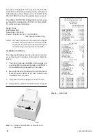
An automatic print-out will be sent to the printer when-
ever the chiller shuts down on a fault, regardless of
whether the fault causes a system or the entire chiller to
lockout or whether restart is permitted. This is the same
print-out that is obtained when the OPER DATA Key is
pressed; however, it will be a snap-shot of system oper-
ating conditions at the instant fault occurred. Additionally,
the Status indication that is noted in the print-out will
note the specific fault that occurred.
Using Other Printers
Control codes vary from printer to printer. This will result
in unusual formatting of printed data from many printers.
In addition, handshaking lines and handshaking se-
quence will differ between printers. This makes the equip-
ment susceptible to operation problems or miswiring
which may cause damage to the printer or the Micropro-
cessor Board. YORK assumes no responsibility for as-
sistance or damage in the use of non-specified printers.
Warranty
YORK assumes no warranty responsibility in the use of
the printer. This includes damages to the printer and the
Microprocessor Boards or chiller operation problems
which may result.
BAS INTERFACE OPTION
(REMOTE RESET OPTION)
The Remote Reset Option allows resetting of the water
temperature setpoint using a 0-10VDC input, a 4-20mA
input, or a dry contact. The electronic circuitry in the
option converts the signals mentioned above into pulse
width modulated (PWM) signals which the microproces-
sor can understand. Whenever an offset is called for, the
change may be noted by the user by pressing the RE-
MOTE RESET TEMP/RANGE Key on the Keypad. All
refresh requirements normally asssociated with PWM
inputs will be automatically taken care of by the elec-
tronics in the option.
It is important to note that the maximum offset, when
this option is installed, is 20°F. This is due to the
electronics limitation of maximum 11 sec. pulse. If a
greater than 20°F offset is required, a user supplied PWM
signal of up to 21 sec. is needed and the Remote Reset
Option cannot be installed.
The Remote Reset Option P/N 471-01232-181 consists
of a Remote Reset printed circuit board, a mounting
bracket and associated wiring. Each of the 3 signal types
will require individual jumpering of the printed circuit board.
This will be discussed in the following text.
0-10VDC
Jumpers JU2 and JU4 must be IN. All other jumpers
should be OUT. Program the REMOTE TEMP SETPOINT
RANGE (page 75) for 40°F which will allow a 20°F offset
with an input of 10VDC. The temperature will be offset
linearly according to the voltage (0-10VDC) applied.
The 0-10VDC signal should be connected to the + and -
terminals on the TB3 Terminal Block at the right of the
Microprocessor Board. Be sure polarity is correct.
CAUTION: THE 0-10VDC INPUT SIGNAL WIRING
MUST NOT BE EARTH GROUNDED!
4-20mA
Jumpers JU3 and JU5 must be IN. All other jumpers
should be OUT. Program the REMOTE TEMP SETPOINT
RANGE (page 75) for 40°F which will allow a 20° F offset
with an input of 20mA. There will be no offset with an
input of 4mA. The temperature will be offset linearly ac-
cording to the current (4-20mA) applied.
The 4-20mA input signal should be connected to the +
and - terminals on the TB3 Terminal Block at the right of
the Microprocessor Board. Be sure polarity is correct.
CAUTION: THE 4-20mA INPUT SIGNAL WIRING
MUST NOT BE EARTH GROUNDED!
Summary of Contents for YCRJ45E00
Page 29: ...FORM 150 24 NM27 YORK INTERNATIONAL 29 CONTROL CIRCUIT With I O Expansion Board LD02106 ...
Page 30: ...30 YORK INTERNATIONAL FIG 9 SYSTEM WIRING ...
Page 31: ...FORM 150 24 NM27 YORK INTERNATIONAL 31 LD02678 ...
Page 35: ...FORM 150 24 NM27 YORK INTERNATIONAL 35 LD02679 ...
Page 36: ...36 YORK INTERNATIONAL MICROPANEL CONNECTION DIAGRAM With I O Expansion Board LD02107 ...
Page 37: ...FORM 150 24 NM27 YORK INTERNATIONAL 37 LD02108 ...

