46
YORK INTERNATIONAL
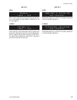
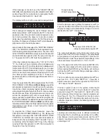
The DAILY SCHEDULE SHUTDOWN message indicates
that the schedule programmed into the CLOCK SET
SCHEDULE/HOLIDAY is keeping the chiller from run-
ning.
Run Permissive is an indicator that an external cycling
contact (i.e. flow switch) connected to terminals 13 and
14 is open, or a system switch(es) on the Microproces-
sor Board is in the OFF position. Whenever the contact
is open or a switch is OFF, the NO RUN PERM will be
displayed.
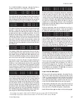
This message informs the operator that the chilled liquid
temperature is below the point (determined by the
setpoint and control range) that the micro will bring the
lead system on, or that the micro has not loaded the
system far enough into the loading sequence to be ready
to bring the lag system ON. The lag system will display
this message until the loading sequence is ready for the
lag system to start (TEMPERATURE DEMAND in the
OPER DATA displays must be 5 or above before cool-
ing load is established for the lag system to run).
STATUS KEY
26572A(D)
GENERAL
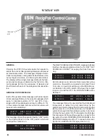
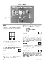
Pressing the STATUS key will enable the operator to
determine current chiller operating status as a whole and
as individual systems. The messages displayed will in-
clude running status, cooling demand, fault status, exter-
nal cycling device status, and anti-recycle timer status.
The display will be a single message relating to the high-
est priority message as determined by the micro. Sta-
tus messages fall into the categories of General and
Fault Status with each of the categories discussed be-
low.
GENERAL STATUS MESSAGE
Each of the general status messages with a description
of its meaning will follow. In the case of messages which
apply to individual systems, SYS 1 and SYS 2 mes-
sages will both be displayed and may be different. Xs
in the sample displays indicate numerical values will
appear in actual displays.
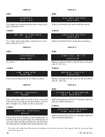
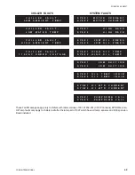
This message informs the operator that the UNIT switch
on the Control Panel is in the OFF position which will
not allow the chiller to run.
STATUS
KEY
U N I T
S W I T C H
I S
I N
T H E
O F F
P O S I T I O N
D A I L Y
S C H E D U L E
S H U T D O W N
S Y S # 1
N O
R U N
P E R M
S Y S # 2
N O
R U N
P E R M
S Y S # 1
N O
C O O L
L O A D
S Y S # 2
N O
C O O L
L O A D
S Y S # 1
C O M P
R U N N I N G
S Y S # 2
C O M P
R U N N I N G
Summary of Contents for YCRJ45E00
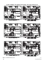
Page 29: ...FORM 150 24 NM27 YORK INTERNATIONAL 29 CONTROL CIRCUIT With I O Expansion Board LD02106 ...
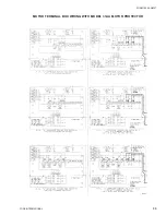
Page 30: ...30 YORK INTERNATIONAL FIG 9 SYSTEM WIRING ...
Page 31: ...FORM 150 24 NM27 YORK INTERNATIONAL 31 LD02678 ...
Page 35: ...FORM 150 24 NM27 YORK INTERNATIONAL 35 LD02679 ...
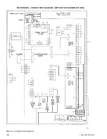
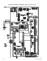
Page 36: ...36 YORK INTERNATIONAL MICROPANEL CONNECTION DIAGRAM With I O Expansion Board LD02107 ...
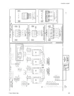
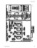
Page 37: ...FORM 150 24 NM27 YORK INTERNATIONAL 37 LD02108 ...

