FORM 150.24-NM27
YORK INTERNATIONAL
19
For installation in equipment rooms adjacent to or near
noise-critical areas, common walls should be of adequate
sound attenuating construction, all doors should be tightly
gasketed, and unit should have vibration isolators.
LOW AMBIENT LOCATIONS
The standard 350 watt crankcase heaters used with the
compressors are suitable for normal standby system
pressures and the ambient temperatures expected in an
indoor engine room heated in the winter. For unheated
engine rooms additional crankcase heat often is needed
to maintain crankcase oil temperatures at levels which
will prevent dilution of oil by the refrigerant to the point
that adequate lubrication on startup is endangered. A
crankcase temperature of 100°F to 120°F should be
maintained.
FOUNDATION AND MOUNTING
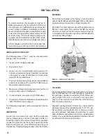
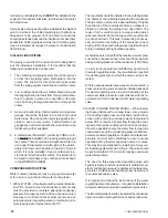
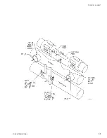
GROUND If the unit is to be located on an earth floor,
it should be placed on a level concrete slab extending 6"
to 8" above the level of the floor (see Fig. 4).
BASEMENT - Remove a portion of the basement floor
so that a concrete base can be poured resting on the
ground, extending 6" to 8" above the basement floor and
having sufficient space on all sides to install corkboard
as shown in Fig. 4.
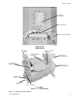
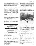
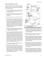
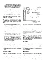
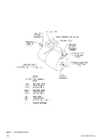
FIG. 5
COMPRESSOR MOUNTING PAD
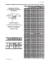
Vibration Isolators (Optional)
When ordered, four (4) vibration isolators will be furnished
with the unit. They are of the level adjusting spring type
and all four isolators are of identical capacity. They should
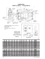
be mounted at the corners of the unit base as shown in
DIMENSIONS.
Fasten the isolator mounting bracket underneath the unit
base (It will be necessary to raise the unit to do this.)
Note that the bolt should be inserted from the bottom of
the mounting bracket.
FIG. 4
FOUNDATIONS
The isolator should be fastened to the mounting bracket
by the cap screw inserted through the hole in the mount-
ing bracket into the tapped hole in the top of the isolator
leveling bolt. Leveling of the unit is accomplished by turn-
ing the leveling bolt. After the unit is level, tighten the
cap screw.
COMPRESSOR MOUNTING
The compressors are mounted on (4) isolator pads (one
under each compressor foot). (See Fig. 5). The mount-
ing bolts are not to be loosened or adjusted at installation.
FIELD WATER PIPING
GENERAL When the unit has been located in its final
position, the unit liquid piping may be connected. Nor-
mal installation precautions should be observed in order
to receive maximum operating efficiencies. Piping should
be kept free of all foreign matter. All condenser and liq-
uid cooler piping must comply in all respects with local
plumbing codes and ordinances.
Since elbows, tees and valves decrease pump capacity,
all piping should be kept as simple as possible.
Hand stop valves should be installed in all lines to facili-
tate servicing.
Piping to the inlet and outlet connections of the chiller
and condenser may include high-pressure rubber hose
or piping loops to insure against transmission of vibra-
tion. This is optional and the necessary components must
be obtained in the field. The unit must not be subjected
to the weight of the connecting piping.
Drain connections should be provided at all low points to
permit complete drainage of condenser, liquid cooler and
piping system.
COMPRESSOR MOUNTING PAD
25112A
LD02350
Summary of Contents for YCRJ45E00
Page 29: ...FORM 150 24 NM27 YORK INTERNATIONAL 29 CONTROL CIRCUIT With I O Expansion Board LD02106 ...
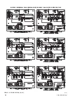
Page 30: ...30 YORK INTERNATIONAL FIG 9 SYSTEM WIRING ...
Page 31: ...FORM 150 24 NM27 YORK INTERNATIONAL 31 LD02678 ...
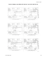
Page 35: ...FORM 150 24 NM27 YORK INTERNATIONAL 35 LD02679 ...
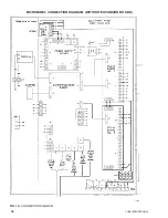
Page 36: ...36 YORK INTERNATIONAL MICROPANEL CONNECTION DIAGRAM With I O Expansion Board LD02107 ...
Page 37: ...FORM 150 24 NM27 YORK INTERNATIONAL 37 LD02108 ...

