YORK INTERNATIONAL
44
which is the Differential Oil Pressure (PSID). This
PSID provided to the Micro Board = Oil Pressure PSIG
– Suction Pressure PSIG. The affected system shuts
down if <10 PSID at run time 4 - 30 seconds; if <25
PSID at run time 30 seconds – 4 minutes: or if <20
PSID at run time > 4 minutes. An F2 (Sys 1) or an F6
(Sys 2) will be displayed for this cut-out.
4. LWT Freeze Safety: This analog signal is sent by
the Leaving Chilled Water Sensor. If the tempera-
ture drops to < 36°F(factory setpoint), the system
shuts down. For Brine applications, the setpoint can
be varied from 20°F to 40°F on the Analog Board by
R25. An F11 code will appear for this safety.
5. LEP (Low Evaporator Pressure Cutout): At run
time = 30 secs to 4 min., the micro checks to see
that suction pressure is 80% cut-out. If not, it shuts
the system down. If the analog signal to the Micro
Board tells the system that the Suction Pressure is
low on 3 consecutive starts, the affected system will
shut down and lock out. See Shutdown Safety Con-
trols, Low Pressure Cutout for trip points. Any time
a system shuts down on a Low Pressure (LP Safety)
a 90 min. timer starts and a “count to 3” counter in
software is incremented to “1”. If the system goes
down 2 more times on a LP Shutdown Safety be-
fore the 90 min. timer times out, the system will shut
down and lock out on a LEP Manual Reset Safety. If
the 90 min. timer times out without 2 more LP shut-
downs, the “count to 3” counter will be cancelled
and reset to “0”. This safety operates like all other
Manual Reset Safeties. An F3 (Sys 1) or an F7 (Sys
2) will be displayed for this cutout.
6. FS(Fault Stop): If external High Discharge Pressure
Cut-out or External Thermal Overload Sensor con-
tacts open, the affected system will shut down. The
manual reset on the sensor (if equipped) must be
reset before the system can be restarted. The exter-
nal HP cutout is set at 395 PSI. An F1 (Sys. 1) or an
F5 (Sys. 2) will be displayed for this safety. Note:
These same codes will also be displayed for a motor
current (power)Fault. This occurs because these safe-
ties do not allow the motor contactor to energize, caus-
ing motor current to be “0”. When a system is to start,
the Micro sends the start signal to the contactor pilot
relay on the Relay Output Board. The pilot relay closes
a contact which applies 115VAC to the motor con-
tactor. If the High Pressure C.O. or motor protector
opens, their contacts which are wired in series with
the pilot relay contacts keep 115VAC from being ap-
plied to the motor contactor. The contactor will not
pull in as the Micro commands or will drop out if pulled
in so the system will shut down on low motor current.
Whenever an F1 or F5 Fault occurs, check discharge
pressure at the time of the fault, motor current at the
time of fault, and also if the H.P. and motor protector
contacts are open.
(YCHA120, 150, 175, & 200)
OTHER SAFETY CONTROLS
1. Suction Pressure: If SYS 1 Suction Pressure ex-
ceeds 105 PSIG, the Micro Board will unload SYS 1
compressor. It will automatically reload SYS 1 when
suction pressure drops below 95 PSIG. If SYS 2 Suc-
tion Pressure exceeds 95 PSIG, the Micro Board will
unload SYS 2 compressor. It will automatically reload
SYS 2 when suction pressure drops below 85 PSIG.
2. Flow Switch: To assure that water flow is present
in the evaporator, the Micro Board senses the Flow
Switch input to the R.P. Relay whose contacts con-
nect to J18 & J19 of the Analog Input Board. If the
Flow Switch opens, both systems will shut down and
will not restart until flow is present. An “A” code will
be displayed. The Flow Switch is connected to ter-
minals 3 & 4 of the terminal block at the bottom right
of the Logic Panel. See Fig. 16.
3. Lead System Fault Override: Whenever the lead
system faults, the Micro automatically switches the
lag system to the lead in an effort to keep chilled
water temperature nearer to setpoint.
REMOTE START/STOP BY A TIME CLOCK, BUILD-
ING AUTOMATION, OR ENERGY MANAGEMENT
SYSTEM
Remote starting and stopping, is accomplished by open-
ing and closing contacts, controlled by a remote source,
connected to the R.P. Relay. These contacts will be wired
in series with the Flow Switch. The Micro Logic Board
looks for the closure of the contacts as a signal to start
the system. Opening the contacts is a signal to stop the
system. See Fig. 16 for connection points.
Since the remote contacts are wired in series with the
Flow Switch, an “A” code will appear on the display when
a REMOTE STOP command is given (contacts open).
If the optional Digital Input Board is used for Remote
Temperature Setpoint Reset, be sure that remote start
and stop is connected in series with the Flow Switch
and not to the Digital Input Board EMS Start and Stop
inputs. These Start and Stop inputs are not active.
“OPTIONAL” REMOTE TEMPERATURE SETPOINT
RESET
Remote Temperature Setpoint Reset capabilities can
be added by adding an optional Digital Input Board and
configuring a jumper/switch on the Micro Logic Board.
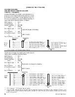
J9 must be IN or Switch #4 must be ON. See Fig. 20
and 21 for the jumper/switch location.
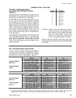
Temperature Setpoint changes are accomplished by clos-
ing the contacts between terminals 11 and 12 on the Digi-
tal Input Board for a defined period of time. The lowest
temperature desired must be set on the panel via the
“Return Water Temperature Setpoint” rotary switches. To
change the setpoint, the contacts between terminals 11
and 12 must be closed for a period between 1 and 1
seconds Closure for a period shorter than 1 second.will
Summary of Contents for YCAQ10
Page 20: ...YORK INTERNATIONAL 20 LD01779 YCHA100 FIG 9 WIRING DIAGRAM YCHA100...
Page 21: ...FORM 150 40 NM20 21 YORK INTERNATIONAL YCHA100 LD01779 D...
Page 22: ...YORK INTERNATIONAL 22 LD01780 L YCHA100 FIG 9 Continued...
Page 23: ...FORM 150 40 NM20 23 YORK INTERNATIONAL LD01780 R YCHA100...
Page 24: ...YORK INTERNATIONAL 24 YCHA100 LD01781 FIG 9 Continued...
Page 25: ...FORM 150 40 NM20 25 YORK INTERNATIONAL LD01782 YCHA100...
Page 46: ...YORK INTERNATIONAL 46 LD01787...
Page 47: ...FORM 150 40 NM20 47 YORK INTERNATIONAL LD01788...
Page 48: ...YORK INTERNATIONAL 48 LD01789...
Page 49: ...FORM 150 40 NM20 49 YORK INTERNATIONAL LD01790...
Page 50: ...YORK INTERNATIONAL 50 LD01791...
Page 51: ...FORM 150 40 NM20 51 YORK INTERNATIONAL LD01792...
Page 77: ......
Page 78: ......
Page 79: ......
Page 80: ......
Page 81: ......
Page 82: ......
Page 83: ......
Page 84: ......
Page 85: ......
Page 86: ......
Page 87: ......
Page 88: ......
Page 89: ......
Page 90: ......
Page 91: ......
Page 92: ......
Page 93: ......
Page 94: ......
Page 95: ......
Page 96: ......
Page 97: ......
Page 98: ......
Page 99: ......

