background image

819682-UIM-A-0212

8

Johnson Controls Unitary Products

SECTION VII: LINE POWER 

CONNECTIONS

Power may be brought into the unit through the supply air end of the
unit (top when unit is vertical) or the left side panel. Use the hole appro-
priate to the unit’s orientation in each installation to bring conduit from
the disconnect. The power lead conduit should be terminated at the
electrical control box. Refer to Tables 11, 12, 14 and 15 to determine
proper wire sizing. Also see Figure 3. To minimize air leakage, seal the
wiring entry point at the outside of the unit.

All electrical connections to air handlers must be made with copper con-
ductors. 

Direct connection of aluminum wiring to air handlers is

not approved.

If aluminum conductors are present, all applicable local and national
codes must be followed when converting from aluminum to copper con-
ductors prior to connection to the air handler.

If wire other than uncoated (non-plated), 75° C ambient, copper wire is
used, consult applicable tables of the National Electic Code (ANSI/
NFPA 70). The chosen condutor and connections all must meet or
exceed the amperage rating of the overcurrent protector (circuit breaker
or fuse) in the circuit.

Additionally, existing aluminum wire within the structure must be sized
correctly for the application according to National Electric Code and
local codes. Caution must be used when sizing aluminum rather than
copper conductors, as aluminum conductors are rated for less current
than copper conductors of the same size.

SECTION VIII: BLOWER SPEED 

CONNECTIONS

All air handlers contain a programmed 5 speed high efficiency brush-
less DC motor.

Adjust blower motor speed to provide airflow within the minimum and
maximum limits approved for evaporator coil, electric heat and outdoor
unit. Speed tap adjustments are made at the motor terminal block, See
Figure 12. Airflow data is shown in Tables 16 and 17.

Connect motor wires to motor speed tap receptacle for speed desired.
See unit wiring label for motor wiring details.
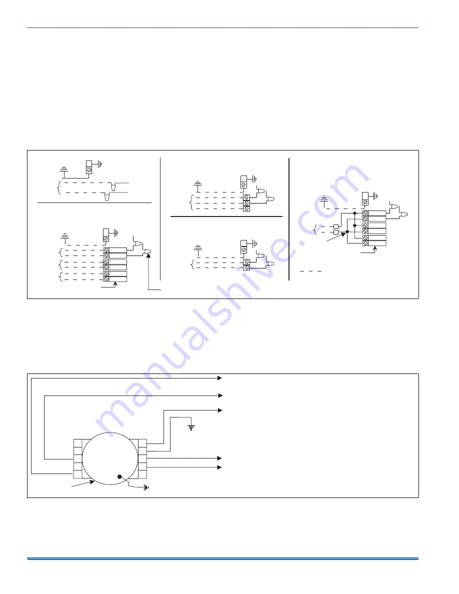
 FIGURE 8:  

Line Power Connections

ELECTRIC HEAT

WITHOUT CIRCUIT BREAKER

SINGLE SOURCE (2.5 - 10 KW)

GND. LUG

POWER
SUPPLY

GND.
LUG

ELECTRIC HEAT

WITHOUT CIRCUIT BREAKER

3 PHASE  (10 - 15 KW)

GND. LUG

POWER
SUPPLY

GND.
LUG

1 PHASE ELECTRIC HEAT

WITH CIRCUIT BREAKER

AS SHIPPED FROM FACTORY

SINGLE SOURCE

(2.5 - 25 KW) - 25 KW SHOWN

GND. LUG

POWER
SUPPLY

GND.
LUG

1 PHASE ELECTRIC HEAT

WITH CIRCUIT BREAKER

& BREAKER BAR REMOVED

MULTI-SOURCE  (15 - 25 KW) - 25 KW SHOWN

GND. LUG

POWER
SUPPLY 1

GND.
LUG

POWER
SUPPLY 2

POWER
SUPPLY 3

TYPICAL WIRING WITHOUT ELECTRIC HEAT

GND. LUG

POWER
SUPPLY

GND.
LUG

POWER WIRING (208/230-1-60)

TERMINAL
BLOCK

TERMINAL
BLOCK

MAY BE 1, 2, OR 3
CIRCUIT BREAKERS

MAY BE 1, 2, OR 3
CIRCUIT BREAKERS

(JUMPER BAR)

CONNECT TRANSFORMER LEADS WITH
WIRE NUTS  (TYPICAL ALL HEAT KITS)

 FIGURE 9:  

Blower Speed Connections

LOW FAN SPEED, CONNECTED
TO LOW FAN TERMINALS ON
CONTROL BOARD, SEE WIRING DIAGRAM

FOR LOW FAN SPEED BEHAVIOR, SEE “LOW FAN”
UNDER “REQUIRED CONTROL SET-UP” SECTION

TO CONTROL BOARD
24V LOW FAN

TO CONTROL BOARD
24V EAC

TO TRANSFORMER
230V

BLOWER

GRN

C

G

L

N

GRN

BLK

WHT

YEL

PUR

RED*

1

2

3

4

5

208/230V
FAN MOTOR

*

Summary of Contents for MX Series

Page 1: ...vailable from Distribution may be applied to the center of the blower access panel The unit can be positioned for bottom return air in the upflow position top return air in the downflow position and r...

Page 2: ...HUD modular home construction practices These instructions are required as a minimum for a safe installation INSPECTION As soon as a unit is received it should be inspected for possible dam age durin...

Page 3: ...document 13 Reposition and replace blower access panel AIR HANDLER AND COIL DOWNFLOW 1 Position blower casing over duct connection and secure such that the supply air end of the blower is down 2 Apply...

Page 4: ...insulation The supply air duct should be properly sized by use of a transition to match unit opening All ducts should be suspended using flexible hang ers and never fastened directly to the structure...

Page 5: ...heater is installed mark the name plate appropriately to indicate that no heat kit is installed The HEAT ENABLE jumper See Figure 10 must be moved to the HEAT position to enable operation of the heat...

Page 6: ...e HEAT position if a heat kit is installed with the air handler With the jumper in the NO HEAT position the control will not energize the heat relay outputs or sense the limit switch input If the jump...

Page 7: ...lay outputs and energize the blower if it wasn t already ener gized When the limit switch closes the control will re energize electric heat according to the thermostat inputs using normal timings Fan...

Page 8: ...ss current than copper conductors of the same size SECTION VIII BLOWER SPEED CONNECTIONS All air handlers contain a programmed 5 speed high efficiency brush less DC motor Adjust blower motor speed to...

Page 9: ...5 6 7 5 4HK 6501006 0 5 Med 3 7 2 9 6 24 6 32 8 3 6 4 8 7 2 9 6 7 2 9 6 4HK16501306 0 5 Med 3 9 8 13 33 3 44 4 3 3 4 3 6 5 8 6 9 8 13 4HK165N1506 0 5 Med 3 10 8 14 4 36 9 49 1 3 6 4 8 7 2 9 6 10 8 14...

Page 10: ...0 110 3 3 4HK16502006 80 94 1 107 5 100 110 3 2 4HK16502506 100 115 7 132 5 125 150 1 1 0 1 O C P Over Current Protection device must be HACR type Circuit Breaker or Time Delay fuse TABLE 12 Electrica...

Page 11: ...4 18 24 1 See conversion Table 10 TABLE 14 Electrical Data For Single Source Power Supply Copper Wire 208 230 3 60 Models Heat Kit Three Phase Heater Amps 240V Field Wiring Min Circuit Ampacity Max O...

Page 12: ...0 70 0 80 0 90 1 00 0 025 0 050 0 075 0 100 0 125 0 150 0 175 0 200 0 225 0 250 MX12B Hi 1 1264 1241 1209 1184 1132 1067 1037 988 821 493 35 40 34 74 33 87 33 16 31 70 29 87 29 04 27 66 22 98 13 81 Me...

Page 13: ...move humidistat jumper on air handler control board 3 For heat pump applications set MODE jumper on air handler control board to the HP position 4 To change quantity of heat during HP defrost cycle re...

Page 14: ...1 and W2 on air handler control board SECTION X MAINTENANCE Filters must be cleaned or replaced when they become dirty Inspect at least once per month The frequency of cleaning depends upon the hours...

Page 15: ...819682 UIM A 0212 Johnson Controls Unitary Products 15 SECTION XI WIRING DIAGRAM FIGURE 13 Wiring Diagram MX12 16...

Page 16: ...otice Published in U S A 819682 UIM A 0212 Copyright 2012 by Johnson Controls Inc All rights reserved Supersedes 628582 UIM A 0111 Johnson Controls Unitary Products 5005 York Drive Norman OK 73069 FIG...

Reviews: