


8
After the unit has either been started or stopped by the timer, the set
time will remain in the program, however the start or stop button must
be pressed again to reset the timer function.
To cancel either the Start or Stop Timer setting press the Cancel
button. To check the time that has been entered either for starting or
stopping the unit, press the appropriate start - stop button and the time
will be displayed. Press the button again to go back to the clock display.
SLEEP TIMER FUNCTION
Sleep mode, which can be used in Cool and Heat modes is a program
in the control which is designed to give a comfortable room environment
during sleeping hours. At the start of sleep mode the unit will operate
in cooling or heating mode continuously until the temperature set point
is reached. It will then run for a further 1 hour period at this setting. After
this, the temperature set point will automatically be 1° C every
hour (cooling) or lowered -1°C every hour (heating) until the sleep (shut
off) time is reached. At this time the unit will shut off.
Sleep mode is set by pressing the sleep button which will set the shut
off time in 30 minute increments, starting from the time shown on the
clock when the sleep button is first pressed.
In sleep mode the unit will follow the settings that were entered at the
time that Sleep mode was started. Sleep mode can be canceled by
pressing the cancel button at any time.
DIAGNOSTIC INFORMATION FUNCTION
The control is equipped with a diagnostic information system to report
operation of the unit as well as operational failures. If your remote
control does not operate properly first check the polarity of the batteries
and that they are in good working condition. Also make sure that the
control is pointed directly at the air conditioning unit when you are using
it, that the distance is a maximum of 10 meters, and that there are no
obstacles between the remote control and the air conditioning unit.
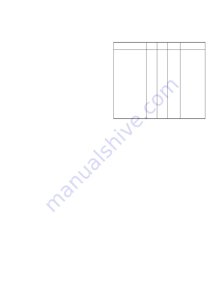
The Diagnostic Information is reported via different flashing patterns
of the 3 indicator lights on the unit. The chart below shows the light
patterns for the various operational, protection and failure modes.
This feature is intended to provide information to the consumer as well
as for service of the units.
Status Power Timer Operation Mode
OFF(with power on)
ON (Temperature satisfied)
Waiting for delay
Compressor started
Sleep mode
Start timer set
Stop timer set
Low HP temp < 18°C
Coil temp > 40°C (cooling)
Overheat > 62° (heating)
Anti Freeze
Low voltage
Sensor fail
Cooling fail
Heating fail
Emergency operation
Test operation
Filter
O
X
X
X
X
X
X
X
X
X
X
F-2
F-1
F-2
F-3
F-3
F-1
F-3
O
O
F-1
O
X
F-2
F-3
O
O
F-1
F-2
O
O
O
O
Note 1
F-1
F-3
Normal Operation
Normal Operation
Normal Operation
Normal Operation
Normal Operation
Normal Operation
Normal Operation
Protection
Protection
Protection
Protection
Protection
Reset-Call Service Technician
Reset-Call Service Technician
Reset-Call Service Technician
Operational
Operational
O
O
O
X
X/O
X/O
X/O
F-1
F-2
F-1
F-2
O
F-1
F-2
F-3
Note 1
F-1
F-3
Notes
1) In emergency mode, the Power light will flash and the other lights will
indicate the operation as above.
2) Lights will flash during the time that the units is held off, due to Low
Voltage. If the voltage has passed through the reset voltage and the
unit is waiting for the time delay, the lights will go to normal operation.
3) The lights will show the LED Diagnostic Code even when the unit is
off.
X = ON, O = OFF, F-1 = ON : 0.5 sec, OFF : 0.5 sec
F-2 = ON : 1.5 sec, OFF : 0.5 sec
F-3 = ON : 0.5 sec, OFF : 1.5 sec


