


361813-UIM-A-0208
2
Unitary Products Group
INSPECTION
As soon as a unit is received, it should be inspected for possible dam-
age during transit. If damage is evident, the extent of the damage
should be noted on the carrier’s delivery receipt. A separate request for
inspection by the carrier’s agent should be made in writing. See Local
Distributor for more information.
LIMITATIONS
The unit should be installed in accordance with all National, State, and
Local Safety Codes and the limitations listed below:
1.
Limitations for the indoor unit, coil, and appropriate accessories
must also be observed.
2.
The outdoor unit must not be installed with any duct work in the air
stream. The outdoor fan is the propeller type and is not designed
to operate against any additional external static pressure.
3.
The maximum and minimum conditions for operation must be
observed to assure a system that will give maximum performance
with minimum service.
4.
The maximum allowable line length for this product is 75 feet.
SECTION III: UNIT INSTALLATION
LOCATION
Before starting the installation, select and check the suitability of the
location for both the indoor and outdoor unit. Observe all limitations and
clearance requirements.
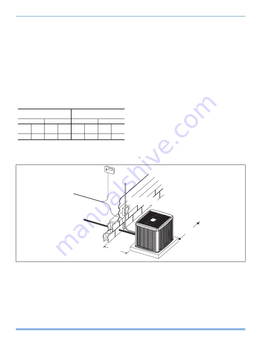
The outdoor unit must have sufficient clearance for air entrance to the
condenser coil, for air discharge, and for service access. See Figure 1.
NOTE:
For multiple unit installations, units must be spaced a minimum
of 18 inches apart. (Coil face to coil face.)
If the unit is to be installed on a hot sun exposed roof or a black-topped
ground area, the unit should be raised sufficiently above the roof or
ground to avoid taking the accumulated layer of hot air into the outdoor
unit.
Provide an adequate structural support.
ADD-ON REPLACEMENT/RETROFIT
The following steps should be performed in order to insure proper sys-
tem operation and performance.
1.
Change-out of the indoor coil to an approved R-22 coil/ condens-
ing unit combination with the appropriate metering device.
2.
If the outdoor unit is being replaced due to a compressor burnout,
then installation of a 100% activated alumina suction-line filter
drier is required, in addition to the factory installed liquid-line drier.
Operate the system for 10 hours. Monitor the suction drier pres-
sure drop. If the pressure drop exceeds 3 psig, replace both the
suction-line and liquid-line driers. After a total of 10 hours run time
where the suction-line pressure drop has not exceeded 3 psig,
replace the liquid line drier, and remove the suction-line drier.
Never leave a suction-line drier in the system longer than 50 hours
of run time.
AIR TEMPERATURE AT
OUTDOOR COIL, °F
AIR TEMPERATURE AT
INDOOR COIL, °F
Min.
Max.
Min.
Max.
DB
Cool
DB
Heat
DB
Cool
DB
Heat
WB
Cool
DB
Heat
WB
Cool
DB
Heat
50
-10
115
75
57
50
1
1. Operation below this temperature is permissible for a short period of
time, during morning warm-up.
72
80
FIGURE 1:
Typical Installation
THERMOSTAT
NEC CLASS 1
WIRING
TO INDOOR
BLOWER
NEC CLASS 2
WIRING
TO COIL
WEATHERPROOF
DISCONNECT SWITCH
48” OVERHEAD
CLEARANCE
24” SERVICE
ACCESS
CLEARANCE
18” FRONT
& SIDES
NOTE:
ALL OUTDOOR WIRING MUST BE WEATHERPROOF
SEAL OPENINGS WITH
PERMAGUM OR EQUIVALENT


