


361813-UIM-A-0208
12
Unitary Products Group
SECTION VI: EVACUATION
It will be necessary to evacuate the system to 500 microns or less. If a
leak is suspected, leak test with dry nitrogen to locate the leak. Repair
the leak and test again.
To verify that the system has no leaks, simply close the valve to the vac-
uum pump suction to isolate the pump and hold the system under vac-
uum. Watch the micron gauge for a few minutes. If the micron gauge
indicates a steady and continuous rise, it’s an indication of a leak. If the
gauge shows a rise, then levels off after a few minutes and remains
fairly constant, its an indication that the system is leak free but still con-
tains moisture and may require further evacuation if the reading is
above 500 microns.
SECTION VII: SYSTEM CHARGE
The factory charge in the outdoor unit includes enough charge for the
unit, a 15 ft. line set and the smallest indoor coil match-up. Some indoor
coil matches may require additional charge. See tabular data sheet pro-
vided in unit literature packet for charge requirements.
The “TOTAL SYSTEM CHARGE” must be permanently stamped on the
unit data plate.
Total system charge is determined as follows:
1.
Determine outdoor unit charge from tabular data sheet.
2.
Determine indoor coil adjustment from tabular data sheet.
3.
Calculate the line charge using the tabular data sheet if line length
is greater than 15 feet.
4.
Total system charge = item 1 + item 2 + item 3.
5.
Permanently stamp the unit data plate with the total amount of
refrigerant in the system.
If a calibrated charging cylinder or accurate weighing device is avail-
able, add refrigerant accordingly. Otherwise, model-specific charging
charts are provided in Tables 3 - 9 for cooling mode only. There is no
accurate method for charging these units in the heating mode. If charg-
ing is required during the heating mode, the unit must be evacuated
and charge weighed in according to the rating plate. If TXV indoor coils
are used with the 2 through 3-1/2 ton models, the following subcooling
charging method must be used. Superheat charging charts are not valid
with TXV equipped systems.
Subcooling Charging Method
For the
heating operation
, there is no accurate subcooling method for
charging the unit. If unit charging is required during heating operation,
the unit must be evacuated and charge weighed-in per the marking on
the rating plate.
For the
cooling operation
, the recommended subcooling is typically
around 10°F. This may vary greatly based on each unique system.
1.
Set the system running in the cooling mode by setting the thermo-
stat at least 6°F below the room temperature.
2.
Operate the system for a minimum of 15-20 minutes.
3.
Refer to the tabular data sheet for the recommended airflow and
verify this indoor airflow (it should be about 400 SCFM per ton).
4.
Measure the liquid refrigerant pressure P and temperature T at the
service valve.
5.
Calculate the saturated liquid temperature ST from Table 2 on the
last page of this document.
6.
Subcooling temperature TC = Saturated Temperature (ST) - Liquid
Temp (T).
Add charge if the calculated subcooling temperature TC in Step 6 is
lower than the recommended level. Remove and recover the refrigerant
if the subcooling TC is higher than the recommended level.
See rating plate for unit specific subcooling chart.
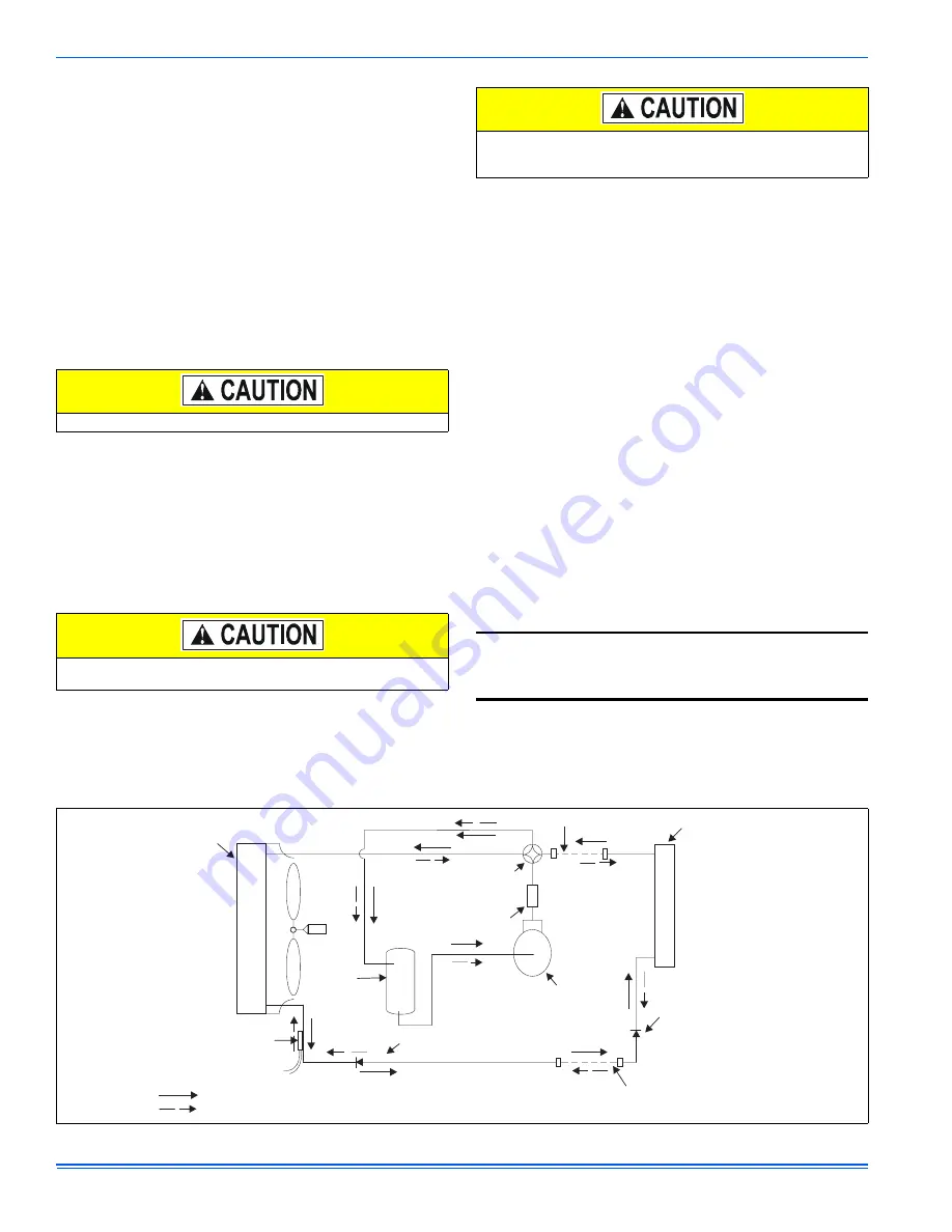
See Figure 12 to trace the flow of refrigerant through the system.
Do not leave the system open to the atmosphere.
Refrigerant charging should only be carried out by a qualified air
conditioning contractor.
Compressor damage will occur if system is improperly charged. On
new system installations, charge system per tabular data sheet for
the matched coil and follow guidelines in this instruction.
Example: The pressure P and temperature T measured at the liquid
service port is 360 Psig and 93°F. From Table 13, the saturated tem-
perature for 360 Psig is 109°. The subcooling temperature TC =
109°-93°=16°F
FIGURE 12:
Heat Pump Flow Diagram
.
TXV
(Cooling)
SHOWN IN COOLING POSITION.
COOLING CYCLE FLOW
HEATING CYCLE FLOW
INDOOR COIL
4-WAY
REVERSING
VALVE
SUCTION
ACCUMULATOR
COMPRESSOR
OUTDOOR
COIL
FIELD CONNECTED LINE
FILTER DRYER
(Solid core)
LIQUID
SENSOR
FIELD CONNECTED LINE
TXV
(Heating)


