


First Stage of Cooling
A call for cooling at terminal Y1 energizes relay RY1. Relay
RY1 closes contacts RY1-1, energizing time delay relay 3TR.
If time delay relay 3TR is satisfied as described below, it will
energize its output terminal Y2, which is connected to
compressor 1 control module terminal M1.
If the compressor 1 control module is satisfied as described
below, it will apply power to terminal 7 of low or high pressure
lock out relay (LOR) contacts. See a description of the LOR
operation below. If the LOR coil is not energized (not locked
out), the LOR contacts will be closed, energizing contactor 1M,
which powers compressor 1 and condenser fan motor 1.
When 1M is energized on H3CE240 units, auxiliary contact
1M-AC2 is closed, powering terminal 1 for opening the stage 1
solenoid in air handlers which feature a stage 1 solenoid.
If the low ambient temperature switch TLA is closed, it will allow
condenser fan 2 contactor 3M to energize. TLA opens as the
temperature falls below 50 F and closes as the ambient rises
above 60 F. TLA is used on the H3CE180, not the H3CE240.
Anti-short Cycle Time Delay Relays 3TR
and 4TR
Relay 3TR, which serves compressor 1 control, has an
adjustable low voltage lock out which is set at 20V in the factory.
The voltage applied to 3TR must be above its lock out setting
and 5 minutes must elapse since the relay was last energized
before it will energize its output terminal Y2. Relay 4TR is
identical but it serves compressor 2 control.
Compressor Control Module
If the compressor control module terminals L1 (or T1) and L2
(or T2) have 24 V applied and the internal compressor
temperature lock out is inactive, the internal switch connecting
M1 and M2 will be closed. M1 to M2 will open if one of the
compressor’s internal temperature sensors exceeds its limit.
M1 to M2 stays open for 30 minutes after a internal temperature
limit is exceeded. The 30 minute lock out may be reset prior to
the 30 minutes expiring by removing power to the control
module terminals L1 and L2. During normal operation, each
compressor control module should always be powered at the
L1 and L2 terminals, whether there is a call for cooling or not.
Low or High Pressure Lock Out Operation
If the lock out circuit path is opened during a call for cooling,
the lock out relay (LOR) coil will energize, opening LOR-1
contacts and disabling all compressor operation. The lock out
circuit path is open if:
•
the lock out relay contacts LOR-1 are open, OR
•
the low pressure switch LP is open AND the low pressure
switch bypass timer contacts 1TR-1 are open, OR
•
the high pressure switch HP is open.
Once the LOR coil has been energized, it remains energized,
locking out cooling operation until the call for cooling has been
removed. When Y1 is returned to 0 volts, the LOR coil is no
longer energized, closing the LOR-1 contacts and removing the
lock out.
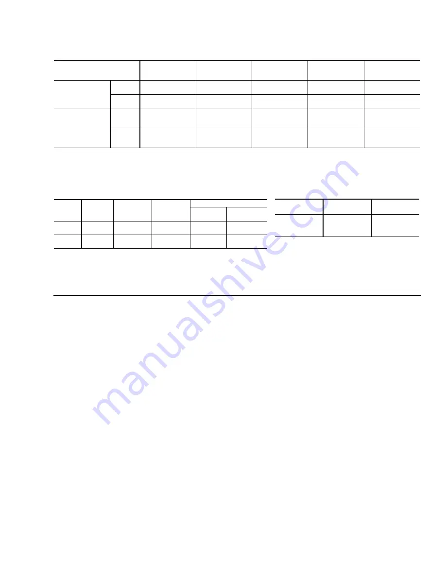
SUCTION LINE DATA
1,2
LIQUID LINE DATA
REFRIGERANT-22 LINE CHARGE
1
Model
Designation
Nominal Capacity
(Tons)
Refrigerant
Flow Rate
3
(Lbs./Min.)
Type L
Copper Tubing
(Inches O.D.)
Refrigerant Gas
Velocity
(FT./Min.)
Friction
Loss
4,5
(PSI/100 Ft.)
HCE180
Full
Capacity
15
45
1-5/8
2-1/8
2300
1360
2.5
0.6
Part
Capacity
8-1/2
25.5
1-5/8
2-1/8
1150
770
6
0.7
0.2
HCE240
Full
Capacity
20
60
1-5/8
2-1/8
2-5/8
3120
1800
1200
4.3
1.2
0.4
Part
Capacity
10
30
1-5/8
2-1/8
2-5/8
1560
900
6
600
6
1.2
0.3
0.1
1All horizontal suction lines should be pitched at least 1 inch every 20 feet in the direction of the refrigerant flow to aid the return of oil to the compressor.
2
Every vertical suction riser greater than 25 feet in height should have a “P” trap at the bottom to facilitate the return of oil to the compressor. Use short radius fittings for these traps.
3
Based on Refrigerant-22 at the nominal capacity of the condensing unit, a suction temperature of 40
°
F and a liquid temperature of 105
°
F.
4
Although suction lines should be sized for a friction loss equivalent to a 2
°
F change in saturation temperature (or approximately 3 psi), sizing the lines for the proper return of oil is more important.
5
These friction losses do not include any allowances for valves or fittings.
6
Since the refrigerant gas velocity may be too low to maintain good oil return up a vertical riser, use the next smaller size. The larger size may be used for horizontal runs for a smaller pressure drop.
Model
Nominal
Capacity
(Tons)
Refrigerant
Flow Rate
1
(Lbs./Min.)
Type L
Copper Tubing
(Inches O.D.)
Pressure Drop
3
Friction
2
(PSI/100 Ft.)
Vertical Rise
(PSI/Ft.)
HCE180
15
45
3/4
7/8
4.7
2.2
0.5
HCE240
20
60
3/4
7/8
8.0
3.5
0.5
1Based on Refrigerant-22 at the nominal capacity of the condensing unit, a liquid temperature of 105
°
F and a
suction temperature of 40
°
F.
2
These friction losses do not include any allowances for a strainer, filter-drier, solenoid valve, isolation valve or fittings.
3
The total pressure drop of the liquid line for both friction and vertical rise must not exceed 40 PSI. If the
pressure drop exceeds 40 PSI, the liquid refrigerant could flash before it reaches the expansion valve. This
flashing will not only cause erratic valve operation and poor system performance, but could also damage the
expansion valve.
Liquid Line
2
Inches, O.D.
5/8
0.113 lb./ft.
7/8
0.237 lb./ft.
Suction Line
2
Inches, O.D.
1-5/8
0.018 lb./ft.
2-1/8
0.031 lb./ft.
2-5/8
0.047 lb./ft.
NOTE: Add the operating charge of the condensing unit, the evaporator
coil and the refrigerant lines to determine the total refrigerant
charge of the system.
1Charges are based on 40
°
F suction temperature and a 105
°
F liquid temperature.
2Type “L” copper tubing.
SEQUENCE OF OPERATION
550.23-TG3Y
Unitary Products Group
7


