York FC9T Series Installation Manual Download Page 6

106633-UIM-A-0205

6

Unitary Products Group

IMPORTANT: 

If an external mounted filter rack is being used see the

instructions provided with that accessory for proper hole cut size.

SECTION III: FILTERS

FILTER INSTALLATION

All applications require the use of a filter. A high velocity filter and a side
return filter rack are provided for field installation. Replacement filter
size is shown in Table 4.

Filters must be installed external to the furnace cabinet. 

DO NOT

attempt to install filters inside the furnace.

SIDE RETURN - FILTER INSTALLATION

Locate and mark the side return opening. Refer to Figure 1 for dimen-
sions of the cutout.

Install the side filter rack following the instructions provided with that
accessory. If a filter(s) is provided at another location in the return air
system, the ductwork may be directly attached to the furnace side
panel.If not provided with the furnace, an accessory filter rack is avail-
able for mounting the filter external to the cabinet.

IMPORTANT: 

Some accessories such as electronic air cleaners and

pleated media may require a larger side opening. Follow the instruc-
tions supplied with that accessory for side opening requirements. Do
not cut the opening larger than the dimensions shown in Figure 1.

SECTION IV: GAS PIPING

GAS SAFETY

IMPORTANT: 

Plan your gas supply before determining the correct gas

pipe entry. Use 90-degree service elbow(s), or short nipples and con-
ventional 90-degree elbow(s) to enter through the cabinet access holes.

GAS PIPING INSTALLATION

Properly sized wrought iron, approved flexible or steel pipe must be
used when making gas connections to the unit. If local codes allow the
use of a flexible gas appliance connection, always use a new listed con-
nector. Do not use a connector that has previously serviced another gas
appliance.

Some utility companies or local codes require pipe sizes larger than the
minimum sizes listed in these instructions and in the codes. The furnace
rating plate and the instructions in this section specify the type of gas
approved for this furnace - only use those approved gases. The instal-
lation of a drip leg and ground union is required. Refer to Figure 4.

IMPORTANT: 

An accessible manual shutoff valve must be installed

upstream of the furnace gas controls and within 6 feet (1.8 m) of the fur-
nace.

The furnace must be isolated from the gas supply piping system by
closing its individual external manual shutoff valve during any pressure
testing of the gas supply piping system at pressures equal to or greater
than 1/2 psig (3.5 kPa).

 FIGURE 2:  

Furnace Base Rectangular Blockoff Panel

TABLE 4: 

Filter Sizes

Input / Output

BTU/H (kW)

CFM 

(m

3

/min)

Cabinet 

Size

Side Return 

Filter in. (cm)

Bottom Return 

Filter in. (cm)

40/38

(11.7/10.8)

1200

(34.0)

A

16 x 25

(41 x 64)

14 x 25

(36 x 64)

60/56

(17.8/16.1)

1200

(34.0)

B

16 x 25

(41 x 64)

16 x 25

(41 x 64)

80/75

(23.4/22.0)

1200

(34.0)

B

16 x 25

(41 x 64)

16 x 25

(41 x 64)

80/75

(23.4/22.0

1600

(45.3)

C

16 x 25

(41 x 64)

20 x 25

(51 x 64)

100/93

(29.3/27.8)

1600

(45.3)

C

16 x 25

(41 x 64)

20 x 25

(51 x 64)

100/93

(29.3/27.8)

2000

(56.6)

C

16 x 25

(41 x 64)

20 x 25

(51 x 64)

120/112

(35.1/32.8)

2000

(56.6)

D

(2) 16 x 25

(2) (41 x 64)

22 x 25

(56 x 64)

All installations must have a filter installed.

Toe Plate

Removable Rectangular
Base Panel.

An overpressure protection device, such as a pressure regulator,
must be installed in the gas piping system upstream of the furnace
and must act to limit the downstream pressure to the gas valve so it
does not exceed 0.5 PSI {14" w.c. (3.48 kPa)}. Pressures exceed-
ing 0.5 PSI {14” w.c. (3.48 kPa)} at the gas valve will cause damage
to the gas valve, resulting in a fire or explosion or cause damage to
the furnace or some of its components that will result in property
damage and loss of life.
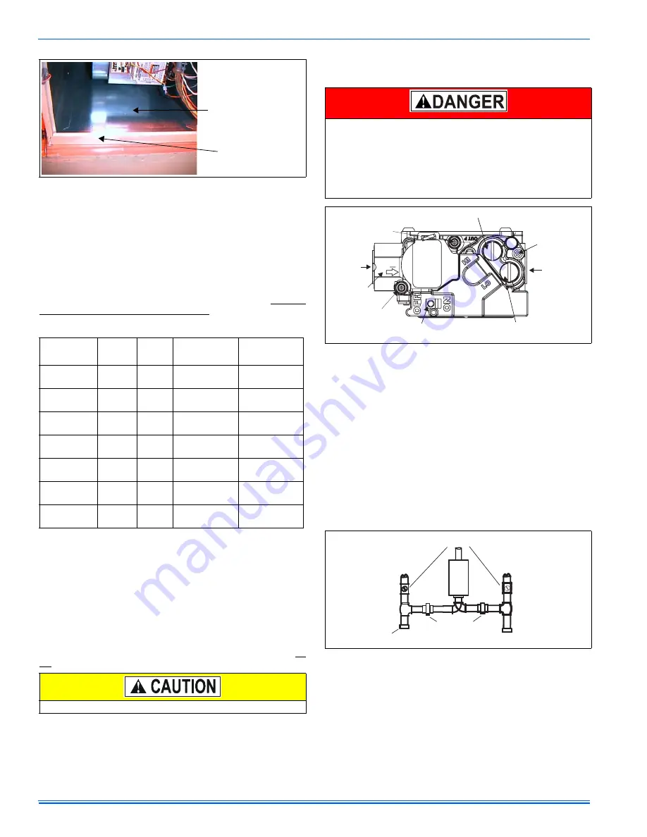
 FIGURE 3:  

Gas Valve

 FIGURE 4:  

Gas Piping

INLET

WRENCH
BOSS

INLET
PRESSURE
PORT

ON OFF
SWITCH

LOW STAGE REGULATOR
ADJUSTMENT

OUTLET

OUTLET
PRESSURE
PORT

VENT
PORT

HIGH STAGE REGULATOR
ADJUSTMENT

EXTERNAL MANUAL
SHUTOFF VALVE

TO GAS
SUPPLY

TO GAS
SUPPLY

GROUNDED JOINT UNION
MAY BE INSTALLED
INSIDE OR OUTSIDE UNIT.

DRIP
LEG

Summary of Contents for FC9T Series

Page 1: ...IST OF SECTIONS SAFETY 1 DUCTWORK 3 FILTERS 6 GAS PIPING 6 ELECTRICAL POWER 8 COMBUSTION AIR AND VENT SYSTEM 9 CONDENSATE PIPING 15 SAFETY CONTROLS 16 START UP AND ADJUSTMENTS 16 WIRING DIAGRAM 23 LIS...

Page 2: ...ational vehicles Failure to carefully read and follow all instructions in this manual can result in furnace malfunction death personal injury and or property damage Furnaces for installation on combu...

Page 3: ...required for passage to the front when servicing or for inspection or replacement of flue vent connections In all cases accessibility clearances shall take precedence over clear ances for combustible...

Page 4: ...the Supply Duct Static Pressure reading to the Return Duct Static Pressure reading and adding the pressure drop across any applied coil TABLES 2 AND 3 are to be used as a guide only to help the instal...

Page 5: ...eal the furnace to plenum connections to prevent air leakage Refer to Figure 1 for unit and plenum dimensions Attic installations must meet all minimum clearances to combustibles and have floor suppor...

Page 6: ...nd in the codes The furnace rating plate and the instructions in this section specify the type of gas approved for this furnace only use those approved gases The instal lation of a drip leg and ground...

Page 7: ...nal pressure Never apply a pipe wrench to the body of the gas valve when installing piping A wrench must be placed on the octag onal hub located on the gas inlet side of the valve Placing a wrench to...

Page 8: ...onnect the green furnace lead equipment ground to the power supply ground An alternate wiring method is to use a field provided 2 5 08 cm x 4 10 2 cm box and cover on the outside of the furnace Route...

Page 9: ...mplete duct system and its own wall thermostat SECTION VI COMBUSTION AIR AND VENT SYSTEM COMBUSTION AIR AND VENT SAFETY This Category IV dual certified direct vent furnace is designed for resi dential...

Page 10: ...els column then look to the right in those rows to the five elbows column It shows N A in the 1 1 2 3 8 cm row so 1 1 2 5 1 cm pipe cannot be used the 2 5 1 cm pipe row shows 40 ft 12 2 m so up to 40...

Page 11: ...0 kW 36 inches 91 cm for models 100 000 BTUH 30 kW Two pipe direct vent applications 9 inches 23 cm for models 50 000 BTUH 15 kW 12 inches 30 cm for models 50 000 BTUH 15 kW Single pipe applications 4...

Page 12: ...stion air systems must be installed so the vent and the combustion air pipes terminate in the same atmospheric zone Refer to Figures 13 or 14 VENTING MULTIPLE UNITS Multiple units can be installed in...

Page 13: ...ical vent Care should be taken to locate side vented systems where trees or shrubs will not block or restrict supply air from entering the terminal Also the terminal assembly should be located as far...

Page 14: ...ht FIGURE 19 Outside and Ambient Combustion Air GABLE VENT GAS VENT SOFFIT VENT VENTILATED ATTIC TOP ABOVE INSULATION OPTIONAL INLET a OUTLET AIR a VENTILATED CRAWL SPACE GAS WATER HEATER VENTILATED A...

Page 15: ...Air The ventilated attic space or a crawl space from which the combustion air is taken must comply with the requirements specified in AIR SOURCE FROM OUTDOORS in this instruction or in Section 5 3 Air...

Page 16: ...CONTROLS These controls are mounted on the burner box assembly If the temper ature in the burner box exceeds its set point the ignition control and the gas valve are de energized The operation of thi...

Page 17: ...ll start and come up to speed Shortly after inducer start up the hot surface igniter will glow for about 17 seconds b After this warm up the ignition module will energize open the main gas valve c Aft...

Page 18: ...3600 then divided by the time it took to measure 0 10 m3 of gas from the gas meter For Propane LP Gas multiply the Heat content of the gas MJ m3 or Default 93 15 times 0 10 m3 of gas measured at the...

Page 19: ...shown in Figure 23 The procedure below is used to adjust either the high fire manifold pressure or the low fire manifold pressure IMPORTANT The cap for the pressure regulator must be removed entirely...

Page 20: ...The fan off timing may be adjusted by positioning the jumper on two of the four pins as shown in Figure 25 The furnace control board also allows user selection of the blower speed that is energized d...

Page 21: ...1225 35 1175 33 1105 31 1045 30 990 28 905 25 890 25 790 22 100 1600 C 80 1600 C HIGH 1960 56 1955 55 1925 55 1890 54 1830 52 1765 50 1695 48 1615 46 1600 45 1485 42 M HI 1565 44 1560 44 1560 44 1575...

Page 22: ...otal system static is 0 58 w c To determine the system airflow complete the follow ing steps Obtain the airflow values at 0 50 w c 125 Pa 0 60 w c 150 Pa ESP Airflow 0 50 2285 CFM 64 70 m3 min Airflow...

Page 23: ...106633 UIM A 0205 Unitary Products Group 23 SECTION X WIRING DIAGRAM FIGURE 26 Wiring Diagram...

Page 24: ...change without notice Printed in U S A 106633 UIM A 0205 Copyright by York International Corp 2005 All rights reserved Supersedes 035 20417 001 Rev C 0904 Unitary 5005 Norman Product York OK Group Dr...

Reviews: