background image

5120416-XIM-C-0216

44

Johnson Controls Unitary Products

Start-Up (Gas Heat)

Pre-Start Check List

Complete the following checks before starting the unit.
1.

Check the type of gas being supplied. Be sure that it is the 
same as listed on the unit nameplate.

2.

Make sure that the vent and combustion hoods have been 
properly installed.

Operating Instructions

Lighting The Main Burners

1.

Turn “OFF” electric power to unit.

2.

Turn room thermostat to lowest setting.

3.

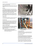
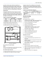
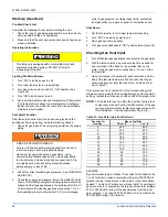
Turn gas valve knob or switch to “ON” position (See 
Figure 29).

4.

Turn “ON” electric power to unit.

5.

Set room thermostat to desired temperature (If thermostat 
“set” temperature is above room temperature, pilot burner 
ignition will occur and, after an interval to prove pilot flame, 
main burners will ignite).

Post Start Checklist

After the entire control circuit has been energized and the 
heating section is operating, make the following checks:
1.

Check for gas leaks in the unit piping as well as the supply 
piping.

2.

Check for correct manifold gas pressures. (See CHECKING 
GAS INPUT.)

3.

Check the supply gas pressure. It must be within the limits 
shown on the rating nameplate. Supply pressure should be 
checked with all gas appliances in the building at full fire. At 
no time should the standby gas pressure exceed 13 in. or 
the operating pressure drop below 5.0 in for natural gas 

units. If gas pressure is outside these limits, contact the 
local gas utility or propane supplier for corrective action.

Shut Down

1.

Set the thermostat to the lowest temperature setting.

2.

Turn “OFF” all electric power to unit.

3.

Open gas heat access panel.

4.

Turn gas valve clockwise to “OFF” position (See Figure 29).

Checking Gas Heat Input

1.

Turn off all other gas appliances connected to the gas meter.

2.

With the furnace turned on, measure the time needed for 
one revolution of the hand on the smallest dial on the 
meter. A typical gas meter usually has a 1/2 or a 1 cubic 
foot test dial.

3.

Using the number of seconds for each revolution and the 
size of the test dial increment, find the cubic feet of gas 
consumed per hour from the Gas Rate - Cubic Feet Per 
Hour Table 21.

If the actual input is not within 5% of the furnace rating (with 
allowance being made for the permissible range of the regulator 
setting), replace the orifice spuds with spuds of the proper size.

NOTE: 

To find the Btu input, multiply the number of cubic feet 
of gas consumed per hour by the Btu content of the gas 
in your particular locality (contact your gas company for 
this information - it varies widely from city to city.).

EXAMPLE
By actual measurement, it takes 13 seconds for the hand on the 
1-cubic foot dial to make a revolution with just a 300,000 Btuh 
furnace running. Read across to the column in the table above, 
headed “1 Cubic Foot”, where you will see that 278 cubic feet of 
gas per hour are consumed by the furnace at that rate. Multiply 
278 x 1050 (the Btu rating of the gas obtained from the local 
gas company). The result is 292,425 Btuh, which is close to the 
300,000 Btuh rating of the furnace.

This furnace is equipped with an intermittent pilot and 
automatic re-ignition system. DO NOT attempt to 
manually light the pilot.

FIRE OR EXPLOSION HAZARD
Failure to follow the safety warning exactly could result 
in serious injury, death or property damage.
Never test for gas leaks with an open flame. use a 
commercially available soap solution made specifically 
for the detection of leaks to check all connections. A fire 
or explosion may result causing property damage, 
personal injury or loss of life.

Table 21: Gas Rate Cubic Feet Per Hour

Seconds for

One Rev.

Size of Test Dial

1/2 cu. ft.

1 cu. ft.

4

450

900

6

300

600

8

228

450

10

180

360

12

150

300

14

129

257

16

113

225

18

100

200

20

90

180

22

82

164

24

75

150

26

69

138

28

64

129

Summary of Contents for DC180

Page 1: ...g 43 Start Up Gas Heat 44 Checking Gas Heat Input 44 Simplicity SE Smart Equipment Firmware Version 3 Basic Unit Control Board Navigation Examples 46 Start Up Service Data Instruction 54 LIST OF TABLE...

Page 2: ...hout economizer or motorized damper option only at the point of installation These gas fired heaters have aluminized steel or optional stainless steel tubular heat exchangers with spark ignition with...

Page 3: ...LP with kit If the information in this manual is not followed exactly a fire or explosion may result causing property damage personal injury or loss of life Do not store or use gasoline or other flamm...

Page 4: ...t 3 Smoke Detector S A 4 Smoke Detector R A 5 Pwr d Conv Outlet Options SS Drain Pan Configuration Options not required for all units These four digits will not be assigned until a quote is requested...

Page 5: ...n this document After installation gas fired units must be adjusted to obtain a temperature rise within the range specified on the unit rating plate If components are to be added to a unit to meet loc...

Page 6: ...CIENCY COMPRESSORS COPPER TUBE ALUMINUM FIN CONDENSER COILS ELECTRICAL DISCONNECT MOUNTING LOCATION Field installed KNOCKOUT FOR SIDE CONTROL WIRING ENTRY KNOCKOUT FOR SIDE POWER WIRING ENTRY SIDE KNO...

Page 7: ...r unit operation Rigging And Handling Exercise care when moving the unit Do not remove any packaging until the unit is near the place of installation Rig the unit by attaching chain or cable slings to...

Page 8: ...A B C D 180 Gas 2300 539 563 612 586 240 Gas 2500 538 563 715 684 300 Gas 3130 615 671 962 882 180 Elec 2100 492 514 558 536 240 Elec 2300 295 517 658 630 300 Elec 2890 487 619 646 508 Unit Size Total...

Page 9: ...84 300 Gas 1420 279 304 436 882 180 Elec 953 223 233 253 536 240 Elec 1043 134 235 299 630 300 Elec 1310 221 281 293 508 Unit Size Total Shipping Weight 6 Point Loads kg A B C D E F 180 Gas 1043 159 1...

Page 10: ...iliary DOT PLUG For pressure Drop Reading FRONT VIEW CONTROL BOX ACCESS 21 5 9 3 4 11 1 2 2 3 4 21 1 2 33 35 5 7 8 46 5 8 7 1 8 6 3 8 VENT AIR OUTLET HOODS COMBUSTION AIR INLET HOOD GAS HEAT ACCESS C...

Page 11: ...wer exhaust option The covering consists of a heavy black paper composition 3 Replace the side supply and return air compartment panels For side duct applications 1 Replace the side panels on the supp...

Page 12: ...n Distance mm in Direction Distance mm in Top1 1 Units must be installed outdoors Over hanging structure or shrubs should not obscure condenser air discharge outlet 1829 72 With 914 36 Maximum Horizon...

Page 13: ...h the dimensions of the duct connections on the unit Refer to Figure 5 for bottom air duct openings Refer to Figure 6 for side air duct openings NOTE It is recommended that in Canada the outlet duct b...

Page 14: ...y on the return air ductwork as close to the unit as possible Cut an opening 16 inches high by 18 inches wide in the ductwork to accommodate the damper Using the holes in the hood flanges as a templat...

Page 15: ...d the same minimum gauge as the replaced wire A disconnect must be utilized for these units Factory installed disconnects are available If installing a disconnect field supplied or York International...

Page 16: ...ed insulated wires should be used to connect the thermostat to the unit Refer to Table 5 for control wire sizing and maximum length Space Sensor The space sensor if used should be located on an inside...

Page 17: ...ge ot required on single stage he g units Jumper is required if there is no Smoke Detector circuit Jumper is required for any co of R RC or RH 5 5 OCC is an output from the thermostat to indicate the...

Page 18: ...E 44 4 50 E18 13 5 1 18 8 44 4 50 E36 26 9 2 37 4 55 2 60 E54 40 4 2 56 2 78 6 80 E72 53 8 2 74 8 83 2 90 240 20 380 3 50 20 7 130 29 2 1 8 2 0 NONE 59 70 E18 11 3 1 17 2 59 70 E36 22 6 2 34 3 59 70 E...

Page 19: ...2 or 4 In 12 304 X 609 X 51 or 102 mm QUANTITY PER UNIT 16 X 20 X 2 or 4 In 4 406 X 508 X 51 or 102 mm QUANTITY PER UNIT 16 X 25 X 2 or 4 In 4 406 X 508 X 51 or 102 mm QUANTITY PER UNIT 18 X 24 X 2 or...

Page 20: ...ction External Shut Off NOTE Maximum capacity of pipe in cubic feet of gas per hour based upon a pressure drop of 0 3 inch W C and 0 6 specific gravity gas Gas Connection The gas supply line can be ro...

Page 21: ...ors and between the second stage regulator and the appliance Pipe size required will depend on the length of the pipe run and the total load of all appliances Complete information regarding tank sizin...

Page 22: ...the control sensors are factory mounted as part of the Factory installed economizer option Power Exhaust Barometric Relief Damper and Rain Hood The instructions for the power exhaust barometric relie...

Page 23: ...ing with a demand from the zone return sensor for the first stage of cooling the dampers modulate to control the supply air temperature to the Economizer Setpoint 1 F If the economizer output is at 10...

Page 24: ...rmistor MAT parameter reports input status F C 3 65 VDC reading MAT to COM with open circuit Read only use in current control revision IN1 MAT LEDs at left on upper edge of economizer board POWER POWE...

Page 25: ...g power exhaust actuator and economizer actuator Connects through circuit trace to 24V IN pin HOT ECON 2 10 VDC output for the Economizer actuator Econ parameter reports output status 0 100 Used to po...

Page 26: ...negative for the indoor air quality sensor Connects through circuit trace to 24V IN pin COM R 24V 24 VAC hot supplied for the outdoor air quality sensor Connects through circuit trace to 24V IN pin H...

Page 27: ...edge of economizer board IN9 PURGE 24 VAC hot input from the PURGE dry contact Purge parameter reports input status False with 0 VAC input True with 24 VAC input When Purge status is True heating and...

Page 28: ...lection force is as follows Tension new belts at the max deflection force recommended for the belt section Check the belt tension at least two times during the first 24 hours of operation Any retensio...

Page 29: ...product at altitude Example 1 What are the corrected CFM static pressure and BHP at an elevation of 5 000 ft if the blower performance data is 6 000 CFM 1 5 IWC and 4 0 BHP Solution At an elevation o...

Page 30: ...ution As in the example above no temperature information is given so 70 F is assumed The 1 5 static pressure given is at an elevation of 5 000 ft The first step is to convert this static pressure to e...

Page 31: ...kW Input kW ESP Pa Output kW Input kW ESP Pa Output kW Input kW HIGH STATIC DRIVE m3 s 1030 6 0 357 2 4 2 8 316 2 8 3 4 253 3 3 3 9 183 3 7 4 5 97 4 2 5 0 1070 5 0 405 2 5 3 0 362 3 0 3 6 298 3 5 4 2...

Page 32: ...nput kW ESP iwg Output bhp Input kW ESP iwg Output bhp Input kW HIGH STATIC DRIVE CFM 895 6 0 1 3 4 7 4 0 1 1 5 0 4 3 0 8 5 6 4 8 0 6 6 1 5 2 0 3 6 8 5 8 930 5 0 1 5 5 0 4 3 1 3 5 3 4 5 1 0 6 0 5 1 0...

Page 33: ...kW ESP iwg Output bhp Input kW ESP iwg Output bhp Input kW HIGH STATIC DRIVE CFM 1030 6 0 1 5 3 1 2 7 1 3 3 6 3 2 1 0 4 3 3 8 0 8 4 9 4 4 0 5 5 6 5 0 1070 5 0 1 7 3 3 2 9 1 4 3 8 3 4 1 2 4 5 4 1 1 0 5...

Page 34: ...ESP iwg Output bhp Input kW ESP iwg Output bhp Input kW HIGH STATIC DRIVE CFM 895 6 0 1 5 3 7 3 2 1 0 4 7 4 0 0 5 5 7 4 9 0 1 6 3 5 4 925 5 0 1 6 3 9 3 4 1 2 4 9 4 2 0 6 6 0 5 1 0 3 6 7 5 7 955 4 0 1...

Page 35: ...750 CFM 10000 CFM ESP iwg OUTPUT bhp INPUT kW ESP iwg OUTPUT bhp INPUT kW ESP iwg OUTPUT bhp INPUT kW 945 6 0 1 0 5 6 4 6 0 3 7 0 5 7 975 5 0 1 2 5 9 4 9 0 5 7 3 6 0 1005 4 0 1 4 6 2 5 1 0 7 7 7 6 3 1...

Page 36: ...ure 22 After readings have been obtained remove the tubes and reinstall the two 5 16 dot plugs that were removed in Step 1 Table 14 Blower Motor And Drive Data MODEL SIZE DRIVE1 1 All 50 Hz DM180 300...

Page 37: ...f the blower speed and belt tension are REQUIRED Tighten blower pulley and motor sheave set screws after these adjustments Re checking set screws after 10 12 hours run time is recommended Table 16 Sta...

Page 38: ...d Compressor 2 is energized provided it has not been locked out and condenser fan motor 1 and condenser fan motor 2 remain energized If the ambient temperature is above 60 F To be available a compress...

Page 39: ...pressor is idle stop the condenser fans If the LPS is still open after the ASCD the compressor will not be energized for 30 seconds The second and third times that the UCB sees an open LPS will count...

Page 40: ...UST use a two stage thermostat a Upon a call for heat by the thermostat the heater contactor M6 will be energized After completing the specified fan on delay for heating the UCB will energize the blow...

Page 41: ...energized The RW2 1 contact is closed energizing the second stage ignition module IC2 IC2 will immediately start the second stage igniter sparking and will open the redundant valve located inside the...

Page 42: ...9 It resets automatically The limit switch operates when a high temperature condition caused by inadequate supply air flow occurs thus shutting down the heater and energizing the blower Auxiliary Limi...

Page 43: ...ce Refer to Table 20 for the required gas heat anticipator setting Start Up Cooling Prestart Check List After installation has been completed 1 Check the electrical supply voltage being supplied Be su...

Page 44: ...time needed for one revolution of the hand on the smallest dial on the meter A typical gas meter usually has a 1 2 or a 1 cubic foot test dial 3 Using the number of seconds for each revolution and th...

Page 45: ...Figure 27 Proper Pilot Flame Adjustment Pilot Checkout The pilot flame should envelope the end of the flame sensor To adjust pilot flame 1 remove pilot adjustment cover screw 2 increase or decrease th...

Page 46: ...is on the top Status line hit the ENTER button This action steps the LCD display into the status mode Hit ENTER to view the status menu Press Enter Step 2 7KH UVW LWHP XQGHU WKH status menu is DVent M...

Page 47: ...ER CANCEL JOY C PWR 7 7 77 Clg Engaged LeadLag Engaged Press Enter Joy Stick Down 2 Step 6 By toggling down twice the screen reaches the ClgOcc SP screen or Cooling Occupied Set Point ENTER CANCEL JOY...

Page 48: ...microprocessor connects through circuit trace to the SD 24 terminal SD 24 24 VAC hot out for factory accessory smoke detector condensate overflow and or user shutdown relay switching in series Connec...

Page 49: ...Lit indicates 24 VAC is present at C and 24V terminals FAULT Red hard lockout networking error and firmware error indicator 1 2 second on off flashing indicates one or more alarm is currently active 1...

Page 50: ...C reading EC2 to EC2 with open circuit Used in suction line temperature safety Pinned connections on right edge of UCB RAH Return Air Humidity input from 0 10 VDC 0 100 RH sensor Input required for re...

Page 51: ...tput for indoor blower contactor coil indoor blower VFD enable relay coil Output with heat cool operation G input or schedule demand C1 24 VAC hot output for compressor 1 If demand is present and perm...

Page 52: ...nter of the board Positive of the 15 VDC reading to C circuit for powering an optional netstat and or Multi Touch gateway C Common for SA BUS power and communication circuits Also incorporated in the...

Page 53: ...C Field Connected BUS BACnet MSTP communication circuit Earth ground reference of the cable to prevent interference on the FC bus BACnet MSTP communication circuit Item Selector in red housing at left...

Page 54: ...rtion of our standard warranty policy which states that Johnson Controls UPG will cover parts and labor on new equipment start up failures that are caused by a defect in factory workmanship or materia...

Page 55: ...ll open position and the frequency drive is operating at 60 HZ Do not proceed with the equipment start up without the design CFM information Design Supply Air CFM __________________________ Design Ret...

Page 56: ...and control complete Air Moving Inspection Completed See Notes Alignment of drive components Belt tension adjusted properly Blower pulleys tight on shaft bearing set screws tight wheel tight to shaft...

Page 57: ...to increase of decrease the airflow to meet the design conditions If the motor pulley size was changed measure the outside diameters of the motor and blower pulleys and record those diameters here Bl...

Page 58: ...Return Air Temperature ________________ F db ________________ F wb ________________ RH Mixed Air Temperature ________________ F db ________________ F wb ________________ RH Supply Air Temperature ____...

Page 59: ...__________________________________________________________________ _______________________________________________________________________________________________________ _____________________________...

Reviews: