


5121495-UIM-D-0516
Johnson Controls Unitary Products
5
4.
Braze the liquid line to the evaporator liquid connection. Nitrogen
should be flowing through the evaporator coil.
5.
Slide the grommet away from the vapor connection at the indoor
coil. Braze the vapor line to the evaporator vapor connection. After
the connection has cooled, slide the grommet back into original
position.
6.
Protect the vapor valve with a wet rag and braze the vapor line
connection to the outdoor unit. The nitrogen flow should be exiting
the system from the vapor service port connection. After this con-
nection has cooled, remove the nitrogen source from the liquid fit-
ting service port.
7.
Replace the Schrader core in the liquid and vapor valves.
8.
Go to SECTION IV for TXV installation.
9.
Leak test all refrigerant piping connections including the service
port flare caps to be sure they are leak tight. DO NOT OVER-
TIGHTEN (between 40 and 60 inch - lbs. maximum).
10. Evacuate the vapor line, evaporator, and liquid line to 500 microns
or less. See Section V.
11.
Replace cap on service ports. Do not remove the flare caps from
the service ports except when necessary for servicing the system.
12. Release the refrigerant charge into the system. Open both the liq-
uid and vapor valves by removing the service valve cap and with
an allen wrench back out counter-clockwise until valve stem just
touches the chamfered retaining wall. If the service valve is a ball
valve, use a Crescent wrench to turn valve stem one-quarter turn
counterclockwise to open. Do not overturn or the valve stem may
break or become damaged. See “PRECAUTIONS DURING
BRAZING SERVICE VALVE”.
13. Replace service valve cap finger tight, then tighten an additional 1/
12 turn (1/2 hex flat). Cap must be replaced to prevent leaks.
14. See “System Charge” section for checking and recording system
charge. See Section VI.
SECTION IV: INDOOR EXPANSION DEVICE
THERMOSTATIC EXPANSION VALVE
(
TXV)
INSTALLATION
The following are the basic steps for installation. For detailed instruc-
tions, refer to the Installation Instructions accompanying the TXV kit.
Install TXV kit as follows:
1.
Relieve the holding charge by depressing schrader core on the suc-
tion manifold stub out.
2. After holding charge is completely discharged, loosen and remove
the Schrader core.
3.
Place a backup wrench on distributor, loosen and remove brass
distributor nut. Retain brass nut for use on liquid line. Keep teflon
washer in place and discard clear disk.
4.
Install the thermal expansion valve to the distributor assembly with
supplied fittings. Ensure teflon washer is seated in distributor. Hand
tighten and turn an additional 1/4 turn to seal. Do not overtighten fit-
tings. See Figure 5.
5.
Slide the nut removed in step 3 over the supplied liquid line. Place
supplied teflon washer from TXV kit in place on TXV, and install liq-
uid line to the top of the thermal expansion valve. Adjust assembly
so liquid line aligns with hole in access panel. Hand tighten the liq-
uid line, and apply an additional 1/4 turn to seal.
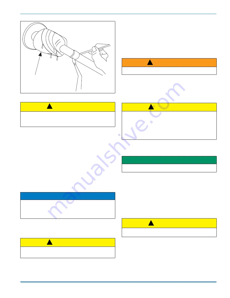
FIGURE 4:
Heat Protection
CAUTION
Do not install any coil in a furnace which is to be operated during
the heating season without attaching the refrigerant lines to the coil.
The coil is under pressure which must be released to prevent
excessive pressure build-up and possible coil damage.
NOTICE
Line set and indoor coil can be pressurized to 250 psig with dry nitro-
gen and leak tested with a bubble type leak detector. Then release
the nitrogen charge.
Do not use the system refrigerant in the outdoor unit to purge or leak
test.
CAUTION
Do not connect manifold gauges unless trouble is suspected. Approx-
imately 3/4 ounce of refrigerant will be lost each time a standard man-
ifold gauge is connected.
$
:(75$*6
:UDSZHWUDJV
DURXQGVHUYLFHYDOYH
RUUHIULJHUDQWOLQHV
SULRUWREUD]LQJ
!
!
WARNING
Never attempt to repair any brazed connections while the system is
under pressure. Personal injury could result.
CAUTION
Outdoor unit model numbers ending with an “H” have a factory
installed hard start kit which is required when a TXV is installed on the
indoor unit. Outdoor unit model numbers with no “H” ending do not
require a hard start kit unless a TXV is being installed on the indoor
unit or unless local regulations dictate it. The Tabular Data Sheet
which comes with the unit specifies whether or not a hard start kit is
required. When a TXV Kit is needed, it should be ordered from
Source 1.
IMPORTANT
Refer to the Technical Guide for the unit to determine the proper TXV
kit to be used on this product.
CAUTION
Do not overtorque. Do not use slip joint pliers. This will distort the alu-
minum distributor and the brass fitting (potentially causing leaks).
!
!
!


