


5121495-UIM-D-0516
6
Johnson Controls Unitary Products
6.
Install the TXV equalizer line onto the vapor line by hand tighten-
ing the 1/4” SAE coupling nut to the equalizer fitting, and apply an
additional 1/3 turn to seal. See Figure 6.
7.
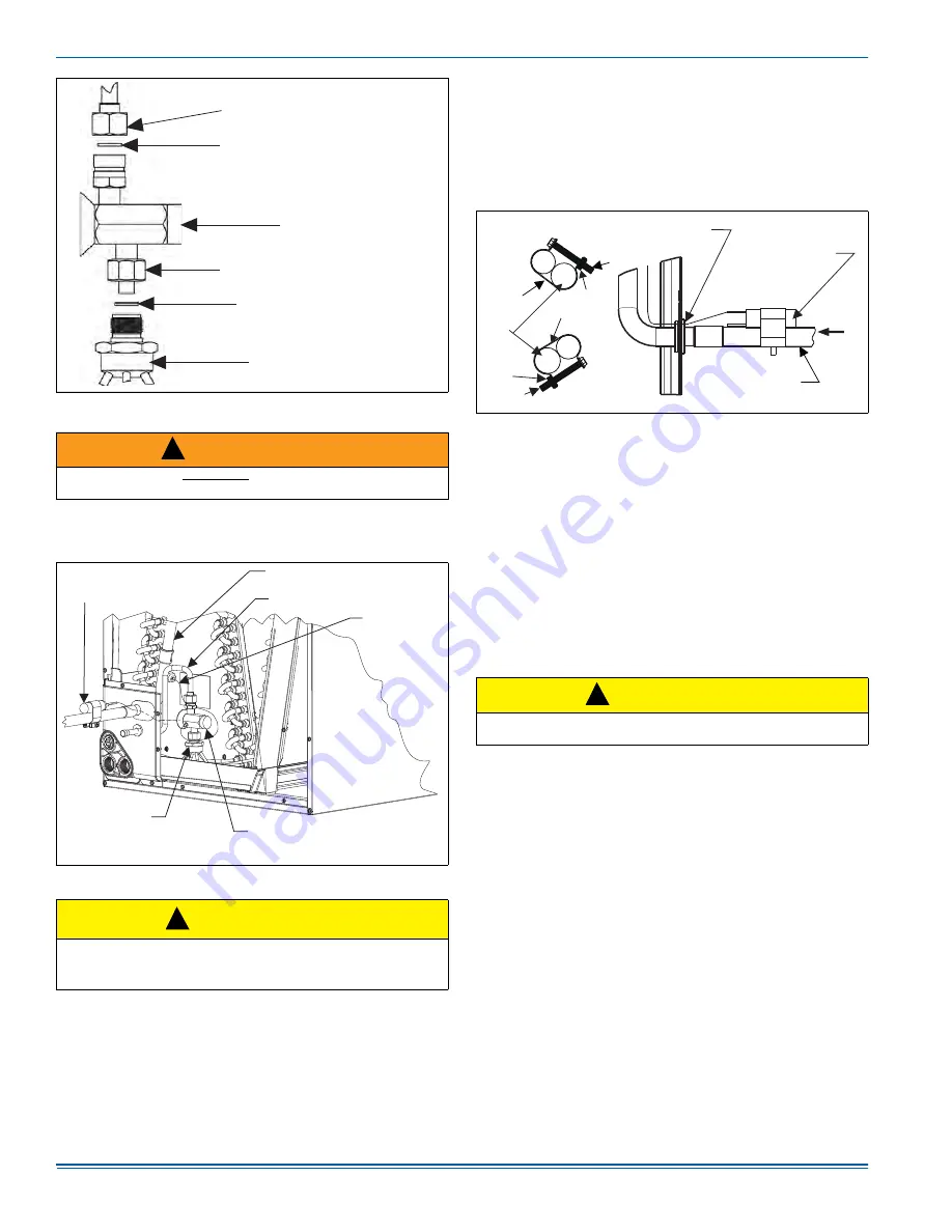
Pass the TXV temperature sensing bulb through the suction line
split grommet in the access panel.
8.
Install the TXV bulb to the vapor line near the cabinet, using the
bulb clamp(s) furnished with the TXV assembly. Ensure the bulb is
making maximum contact. See Figures 6 and 7.
a.
If possible, install the temperature bulb on a horizontal run of
the vapor line. Ensure that the bulb is installed at a 10 o’clock
or 2 o’clock position. See Figure 7.
b.
If bulb installation is made on a vertical run, ensure that the
bulb is a minimum of 8 inches (20.3 cm) away from elbow
coming out of the coil. Position the bulb with the tail of the
bulb at the top, so that the bulb acts as a reservoir.
c.
Insulate the bulb using thermal insulation provided to protect
it from the effect of the surrounding ambient temperature.
Cover completely to insulate.
9.
After line set is installed, leak test the system.
SECTION V: EVACUATION
It will be necessary to evacuate the system to 500 microns or less. If a
leak is suspected, leak test with dry nitrogen to locate the leak. Repair
the leak and test again.
To verify that the system has no leaks, simply close the valve to the
vacuum pump suction to isolate the pump and hold the system under
vacuum. Watch the micron gauge for a few minutes. If the micron
gauge indicates a steady and continuous rise, it’s an indication of a
leak. If the gauge shows a rise, then levels off after a few minutes and
remains fairly constant, it’s an indication that the system is leak free but
still contains moisture and may require further evacuation if the reading
is above 500 microns.
SECTION VI: SYSTEM CHARGE
To ensure that your unit performs at the published levels, it is important
that the indoor airflow is determined and refrigerant charge added
accordingly.
MEASURE INDOOR AIR FLOW
To determine rated air flow for a specific match, consult the technical lit-
erature at www.upgnet.com. When attempting to match this air flow,
select the lowest possible speed tap, measure the actual flow, and
adjust as necessary.
To measure actual air flow, it is not an acceptable method to just
check the jumper pin setting tables and is to assume 0.5” water
column total external static pressure.
To determine indoor air flow, first measure the static pressure with a
manometer between the filter and blower. On a single-piece air handler,
take a second reading after the coil. On a furnace or modular air han-
dler, take the second reading after the heat exchanger, but before the
indoor coil. Add the negative return static to the positive supply static to
determine the system total static pressure. Treat the negative return
static as a positive pressure (even though it is a negative reading). If
there is static pressure on the blower (i.e. -.10) return, add it to a supply
static (.40) which equals a (.50) total system static pressure. Compare
this value to the table for the indoor unit's static pressure vs. CFM or to
a curve chart.
FIGURE 5:
TXV Installation
WARNING
Schrader valve core MUST NOT be installed with TXV installation.
Poor system performance or system failure could result.
FIGURE 6:
TXV Bulb and Equalizer Line Installations
CAUTION
In all cases, mount the TXV bulb after vapor line is brazed and has
had sufficient time to cool. Failure to use suction line grommet may
result in premature TXV failure.
T
X
V
/
D
I
STR
IB
UTOR
COUP
LING
LI
QU
I
D
LIN
E
/
T
X
V
COUP
LING
TE
FL
O
N W
AS
H
ER
T
X
V
TE
FL
O
N W
AS
H
ER
D
I
STR
IB
UTOR
A
0281-001
!
A
0279-001
TV
X
EQUA
LIZ
ER
LIN
E
D
I
STR
IB
UTOR
B
OD
Y
T
H
ER
M
A
L
E
X
PA
N
S
I
O
N
VA
L
VE
(
T
X
V
)
LI
QU
I
D
LIN
E
VAPOR
LIN
E
T
X
V
B
U
LB
(Wrap with
insulation.)
!
FIGURE 7:
Proper Bulb Location
CAUTION
Refrigerant charging should only be carried out by a licensed quali-
fied air conditioning contractor.
T
X
V
B
U
LB
(
C
over completely
with insulation.)
VAPOR
LIN
E
O
F LIN
E
SET
A
0269-002
C
L
A
M
P
A
DETAIL A
T
X
V
SE
N
S
ING B
U
LB
(
P
ass through split hole
in grommet.)
VAPOR
LIN
E
N
UT
N
UT
Bulb at
10 o’clock
position.
Bulb at
2 o’clock
position.
SCRE
W
SCRE
W
C
L
A
M
P
!


