background image

352867-UIM-A-0208

Unitary Products Group

5

SECTION IV: ORIFICE INSTALLATION

Install Schrader Valve Core and Orifice as follows:

1.

Slide indoor coil out of cabinet far enough to gain access to equal-
izer fitting on the suction line.

2.

After holding charge is completely discharged remove black plas-
tic cap on equalizer fitting.

3.

Install Schrader Valve Core supplied with the outdoor unit into
equalizer fitting using a valve core tool.

4.

Loosen and remove the liquid line fitting from the orifice distributor
assembly.  Note that the fitting has right hand threads.

5.

Install proper size orifice supplied with outdoor unit.  Refer to sup-
plied Tabular Data Sheet for specific orifice size and indoor coil
match up.

6.

After orifice is installed reinstall the liquid line to the top of the ori-
fice distributor assembly.  Hand tighten and turn an additional 1/8
turn to seal.  Do not over tighten fittings.

7.

Leak test system.

8.

Replace black plastic cap on equalizer fitting.

9.

Slide indoor coil back into cabinet.

SECTION V: TXV INSTALLATION

The following are the basic steps for installation. For detailed instruc-
tions, refer to the Installation Instructions accompanying the TXV kit.
Install TXV kit as follows:

IMPORTANT: 

Only 1TVM900 series valves are to be used on this prod-

uct.

1.

Relieve the holding charge by pulling off the rubber cap plug on
the suction manifold line of the coil.

2.

After holding charge is completely discharged, loosen and remove
the schraeder cap seal.

3.

Loosen and remove distributor cap seal.

4.

Install the thermal expansion valve to the orifice distributor assem-
bly with supplied fittings. Hand tighten and turn an additional 1/4
turn to seal. Do not overtighten fittings.

5.

Install the liquid line to the top of the thermal expansion valve with
fitting supplied with the liquid line. Hand modify the liquid line to
align with casing opening. Hand tighten the liquid line and an addi-
tional 1/4 turn to seal.

6.

Install the TXV equalizer line into the vapor line as follows:

a.

Hand tighten the 1/4” SAE nut to the schraeder fitting and an
additional 1/3 turn to seal.

7.

Install the TXV bulb to the vapor line near the equalizer line, using
the bulb clamp(s) furnished with the TXV assembly. Ensure the
bulb is making maximum contact.

a.

Bulb should be installed on a horizontal run of the vapor line if
possible. The bulb should be installed on top of the line.

b.

If bulb installation is made on a vertical run, the bulb should
be located at least 16 inches from any bend, and on the tub-
ing sides opposite the plane of the bend. The bulb should be
positioned with the bulb tail at the top, so that the bulb acts as
a reservoir.

c.

Bulb should be insulated using thermal insulation provided to
protect it from the effect of the surrounding ambient tempera-
ture. Cover completely to insulate from air-stream.

SECTION VI: EVACUATION

It will be necessary to evacuate the system to 500 microns or less. If a
leak is suspected, leak test with dry nitrogen to locate the leak. Repair
the leak and test again. 

To verify that the system has no leaks, simply close the valve to the vac-
uum pump suction to isolate the pump and hold the system under vac-
uum. Watch the micron gauge for a few minutes. If the micron gauge
indicates a steady and continuous rise, it’s an indication of a leak. If the
gauge shows a rise, then levels off after a few minutes and remains
fairly constant, it’s an indication that the system is leak free but still con-
tains moisture and may require further evacuation if the reading is
above 500 microns.

SECTION VII: SYSTEM CHARGE

The factory charge in the outdoor unit includes enough charge for the
unit, a 15 ft. line set, and the smallest indoor coil match-up. Some
indoor coil matches may require additional charge. See tabular data
sheet provided in unit literature packet for charge requirements.

The “TOTAL SYSTEM CHARGE” must be permanently stamped on the
unit data plate.

Total system charge is determined as follows:

1.

Determine outdoor unit charge from tabular data sheet.

2.

Determine indoor coil adjustment from tabular data sheet.

3.

Calculate the line charge using the tabular data sheet if line length
is greater than 15 feet.

Failure to install Schrader Valve Core on orifice applications could
result in total refrigerant loss of the system!
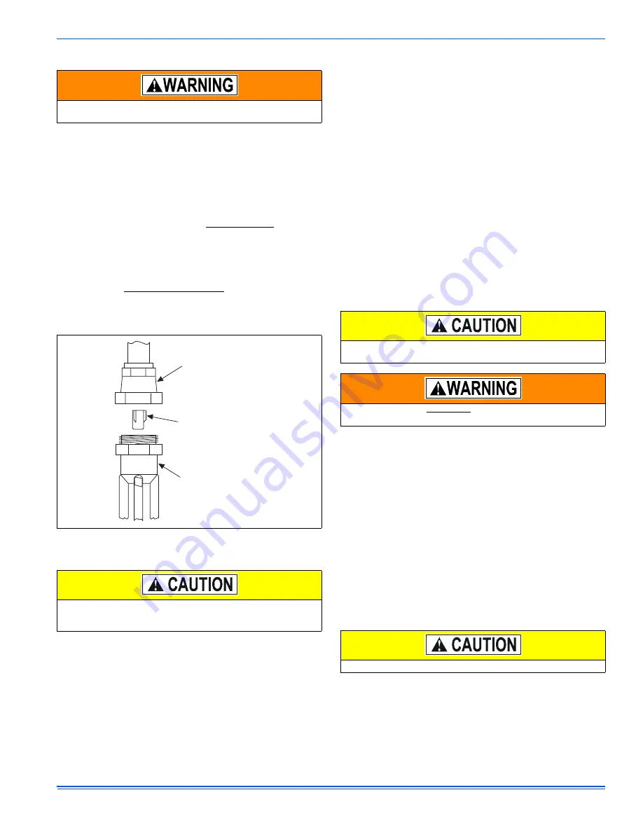
 FIGURE 5:  

Orifice Installation

When using a TXV, 13 SEER models 12-48 require a hard start kit.
Models 12-48 with a “H” on the end of the model number have a
factory installed hard start.

LIQUID LINE
SWIVEL COUPLING
(This fitting is a right-hand thread,
turn counter-clockwise to remove)

ORIFICE

DISTRIBUTOR

 In all cases, mount the TXV bulb after vapor line is brazed and has
had sufficient time to cool.

Schrader valve core MUST NOT be installed with TXV installation.
Poor system performance or system failure could result.

Do not leave the system open to the atmosphere.

Summary of Contents for 13 Seer-CCJD Series

Page 1: ...es refrigerant containers and recovery system must be designed to handle the POE type oils and the higher pressures of R 410A Manifold sets should be 800 PSIG high side and 250 PSIG low side with 550 PSIG low side restart All hoses must have a 700 PSIG service pressure rating Leak detectors should be designed to detect HFC refrigerant Recovery equipment including refrigerant recovery containers mu...

Page 2: ... and performance Line set change out is also recommended 1 Change out of the indoor coil to an approved R 410A coil con densing unit combination with the appropriate metering device 2 Change out of the line set when replacing an R 22 unit with an R410 A unit is highly recommended to reduce cross contamina tion of oils and refrigerants 3 If change out of the line set is not practical then the follo...

Page 3: ...ufficient refrigerant flow Slope horizontal vapor lines at least 1 every 20 feet toward the outdoor unit to facilitate proper oil return PRECAUTIONS DURING LINE INSTALLATION 1 Install the lines with as few bends as possible Care must be taken not to damage the couplings or kink the tubing Use clean hard drawn copper tubing where no appreciable amount of bending around obstruction is necessary If s...

Page 4: ...s including the service port flare caps to be sure they are leak tight DO NOT OVER TIGHTEN between 40 and 60 inch lbs maximum NOTE Line set and indoor coil can be pressurized to 250 psig with dry nitrogen and leak tested with a bubble type leak detector Then release the nitrogen charge NOTE Do not use the system refrigerant in the outdoor unit to purge or leak test 10 Evacuate the vapor line evapo...

Page 5: ...possible The bulb should be installed on top of the line b If bulb installation is made on a vertical run the bulb should be located at least 16 inches from any bend and on the tub ing sides opposite the plane of the bend The bulb should be positioned with the bulb tail at the top so that the bulb acts as a reservoir c Bulb should be insulated using thermal insulation provided to protect it from t...

Page 6: ...ing value 5 Measure and record the pressure at the liquid valve pressure port and compare to the value obtained in step 4 6 Add charge if the measured liquid pressure is lower than the rec ommended value Remove recover charge if the measured liquid pressure is above the recommended value Condenser subcooling is obtained by calculating the difference of the saturated refrigerant temperature of the ...

Page 7: ... to be in accordance with national electrical codes NEC and or local city codes NOTE A Start Assist Kit is available and recommended for long line set applications or in areas of known low voltage problems 5 Mount the thermostat about 5 ft above the floor where it will be exposed to normal room air circulation Do not place it on an out side wall or where it is exposed to the radiant effect from ex...

Page 8: ...tric heat on thermostat is not necessary MA SHP AHP ID MODELS Other Part Numbers SAP Legacy 265902 031 09167 2 Part Numbers SAP Legacy 159480 031 09156 1 COM 24 Volt Common R 24 Volt Hot W2 Second Stage Heat O Reversing Valve Energized in Cool X L Malfunction Light HUM Humidity Switch Open on Humidity Rise PSC AIR HANDLER CONTROL G Fan PSC AIR HANDLER 1 EAC 24 VAC out Electronic Air Cleaner HUM OU...

Page 9: ...ngle Stage Compressor Y Y2 Second or Full Stage Compressor W1 First Stage Heat Y Full Stage Compressor G Fan BP11C50124 BN11C01124 DP11C40124 DN11C00124 THERMOSTAT RH 24 Volt Hot Heat XFMR RC 24 Volt Hot Cool XFMR W Full Stage Heat Selection of GAS ELEC switch on thermostat is not necessary C 24 Volt Common Y Full Stage Compressor G Fan BN11C00124 THERMOSTAT RH 24 Volt Hot Heat XFMR RC 24 Volt Hot...

Page 10: ...age Heat Clipping Jumper W914 for electric heat on thermostat is not necessary 24VAC Humidifier Optional C 24 Volt Common Y Compressor SINGLE STAGE AIR CONDITIONER Y Compressor Contactor SINGLE STAGE AIR CONDITIONER SINGLE STAGE AIR CONDITIONER G8C L Y M 8S G 9F G 8 9 S ID MODELS G T GLS TG 8 9 S LF8 GF 8 9 C 24 Volt Common R 24 Volt Hot W Full Stage Heat SINGLE STAGE PSC FURNACE G Fan SINGLE STAG...

Page 11: ...tat is not necessary C 24 Volt Common Y Full Stage Compressor G Fan BN11C00124 THERMOSTAT RH 24 Volt Hot Heat XFMR RC 24 Volt Hot Cool XFMR W Full Stage Heat Thermostat Installer Setup 1 System Type must be set to 0 C 24 Volt Common Thermostat Installer Setup 15 Compressor Protection must be set to 5 External Humidistat Optional Open on Humidity Rise G8C L Y M 8S G 9F G 8 9 S ID MODELS G T GLS TG ...

Page 12: ...e installer should also instruct the owner on proper operation and maintenance of all other system components MAINTENANCE 1 Dirt should not be allowed to accumulate on the outdoor coils or other parts in the air circuit Clean as often as necessary to keep the unit clean Use a brush vacuum cleaner attachment or other suitable means 2 The outdoor fan motor is permanently lubricated and does not requ...

Reviews: