5052617-UIM-E-1116
Johnson Controls Unitary Products
33
After about 5 minutes of operation, determine the furnace temperature
rise. Take readings of both the return air and the heated air in the ducts,
about six feet (1.83 m) from the furnace where they will not be affected
by radiant heat. Increase the blower speed to decrease the temperature
rise; decrease the blower speed to increase the rise. See furnace rating
plate for minimum or maximum temperature rise, and adjust blower
speed accordingly.
ADJUSTMENT OF FAN CONTROL SETTINGS
Heating Indoor Fan Off Delay
This furnace is equipped with a time-on/time-off heating fan control. The
fan on delay is fixed at 30 seconds. The fan off delay has 4 settings (60,
90, 120 and 180 seconds). The fan off delay is factory set to 120 sec-
onds. The fan-off setting must be long enough to adequately cool the
furnace, but not so long that cold air is blown into the heated space.
The BLOWER OFF DELAY timing may be adjusted by positioning the
dipswitches shown in Figure 40.
This furnace is equipped with a standard ECM motor. Blower motor
speed taps are located on the furnace control board in the blower com-
partment.
Refer to Figure 40 and the unit wiring diagram label to change blower
speed. Place all unused motor leads on the PARK terminal. One park
terminal is provided. To use same speed tap for heating and cooling,
the terminals must be jumped together at the furnace control board
using a field supplied jumper. This control has a continuous fan speed
dipswitch. On a fan call only (G), the control will energize which ever
blower tap is selected by dipswitches. This control will change other
blower speeds on 24V thermostat inputs (Y1, Y/Y2, W, W2).
TAKING A FLUE GAS SAMPLE
If it becomes necessary to obtain a flue gas sample for analysis, it is
permissible to drill a small hole in the plastic flue pipe for a sample
probe, provided that the vent piping is PVC and the hole is properly
sealed afterwards. If using a polypropylene vent system, the vent sys-
tems manufacturer test port fitting must be used. DONOT drill a test
port hole in polypropylene piping. Use the following procedure:
1.
Drill a 11/32" hole in the side wall of the PVC vent pipe. If the hole is
in a horizontal section of the vent pipe, ensure that it is located
away from the bottom where condensation may be flowing back
toward the furnace.
2.
Operate the furnace a minimum of (10 minutes) to ensure stable
operation of the combustion process.
3.
Sample the flue gas as necessary to obtain CO readings.
4.
Using a 1/8" pipe tap, cut threads into the sampling hole of the PVC
pipe.
5.
Use high temp RTV as a sealant on the threads of a 1/8" brass
MPT plug and insert it 3 turns into the hole to correctly seal it.
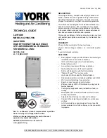
EXTERNAL STATIC PRESSURE SETUP
Set appropriate airflow per temperature rise for gas heating. Set appro-
priate airflow per Table 14 for cooling/heat pump heating operating
based on outdoor unit size.
To measure external static pressure:
•
Measure the supply air static pressure
•
Record this positive number
•
Measure the return air static pressure
•
Record this negative number
•
Treat the negative number as a positive and add the two num-
bers together
•
This is total system static
FIGURE 39:
Measuring External Duct Static
S
upply Duct
Return
Duct
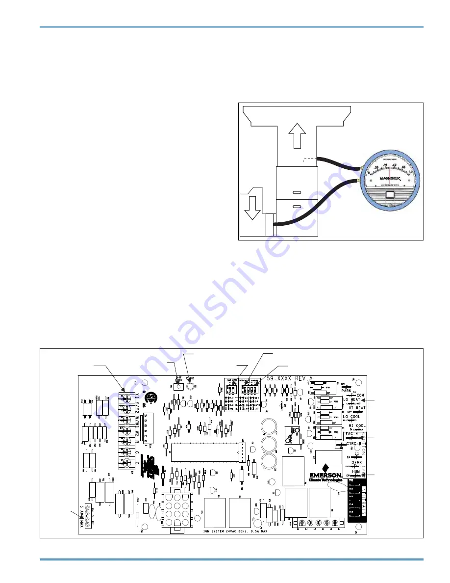
FIGURE 40:
Furnace Control Board
&219(17,21$//2:
92/7$*(7+(50267$7
&211(&7,216
',$*1267,&/,*+7
',$*1267,&(5525
&2'(5(75,(9$/
%87721
&217,18286)$1
63(('',36:,7&+(6
%/2:(52))'(/$<
6(77,1*',36:,7&+(6
+,*+/2:),5(
67$*,1*',36:,7&+(6
(/(&7521,&
$,5&/($1(5
7(50,1$/
+80,',),(5
7(50,1$/
$
%/2:(5
02725
/2:92/7$*(
&211(&7256
&21752/
%2$5'
)86(