


035-19671-001 Rev. A (0404)
Unitary Products Group
7
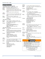
Hot Surface Ignition System
FURNACE CLEANING SECTION
NOTE:
The cleaning operations listed below must be performed only by
a qualified service agency.
Burner Removal/Cleaning
The main burners should be checked periodically for dirt accumulation.
If cleaning is required, follow this procedure:
1.
Turn off the electrical power to the unit.
2.
Turn off the gas supply at the external manual shut-off valve and
loosen the ground union joint.
3.
Remove the upper access panel and remove the burner box
cover.
4.
Disconnect wires from flame sensor, rollout switch and HSI igniter.
Remove igniter carefully, as it is easily broken.
5.
Remove the screws that hold the burner box assembly to the vest
panel and remove the assembly.
6.
Remove burners from the burner assembly.
7.
Burners may be cleaned by rinsing in hot water.
8.
Reassemble the burners in the reverse order.
Cleaning the Heat Exchanger
Lower Heat Exchanger Access
1.
Turn off the electrical power to the unit and turn off gas supply at
the shutoff valve.
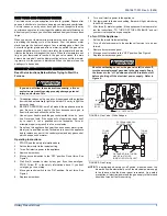
2.
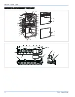
Remove the blower and burner compartment access doors. Dis-
connect the gas supply piping at the union to permit removal of the
entire burner and gas control assembly from the vestibule panel.
Use the wrench boss on the gas valve when removing or installing
this piping. See Figure 4.
3.
Unplug the igniter from the wire harness. Disconnect sensor and
rollout switch wires located on top of the air shield. Identify and
note the location of all leads for ease of reinstallation. Also discon-
nect the wires at the side rollout switches (upflow only) and the
gas valve wires.
4.
Remove the screws holding the burner assembly to the vestibule
panel and remove this assembly. Handle the assembly carefully
since it contains the igniter, which is fragile and easily broken. The
lower portion of the heat exchanger will now be exposed. To clean
the burner assembly, use a vacuum cleaner, or remove the burn-
ers as outlined in burner cleaning, and clean in hot water.
Upper Heat Exchanger Access
1.
Perform steps 1-4 above.
2.
Disconnect vent piping from the vent motor assembly at the top
panel on the furnace (upflow only). On downflow models, the vent
pipe is attached to the vent motor out-let. Remove this screw
before proceeding.
3.
Unplug the vent motor wires and ground wire. Remove the pres-
sure switch tubing at the tap on the vent motor housing.
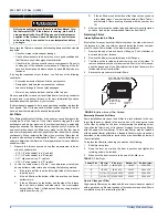
NOTE:
It is recommended that replacement gaskets be avail-able
before removing vent motor.
1.
Remove six mounting screws that hold the vent motor to the
restrictor plate. The surface is gasketed and gasket can be reused
if it is carefully removed. It is necessary to remove this assembly to
gain access to the restrictor plate mounting holes. The assembly
may be vacuumed if cleaning is necessary. If any vent assembly
parts are damaged, replace with an entire new assembly (except
for gaskets).
2.
Remove the perimeter screws attaching the restrictor plate assem-
bly to the vestibule panel. The surface is also gasketed. The
assembly, including the flue baffle plate (rear) may be vacuumed
or cleaned with hot water if necessary.
3.
The upper portion of the heat exchanger is now accessible. With a
long flexible wire brush, clean inside each tube at both the top and
bottom. The brush must pass around the rear heat exchanger
tubes. Vacuum loose scale and dirt from each tube.
4.
Clean - Replace all components in reverse order. Re-gasket all
surfaces which required a gasket. Reconnect all wiring. Reattach
vent pipe and gas supply lines before restoring service to furnace.
Restore electrical power, check gas supply piping for leaks, and
then verify furnace operation.
TROUBLESHOOTING
The following visual checks should be made before troubleshooting:
1.
Check to see that the power to the furnace and the ignition control
module is ON.
2.
The manual shut-off valves in the gas line to the furnace must be
open.
3.
Make sure all wiring connections are secure.
4.
Review the sequence of operation. Start the system by setting the
thermostat above the room temperature. Observe the system’s
response. Then use the troubleshooting section in this manual to
check the system’s operation.
TABLE 2:
Replacement PSC Motor / Capacitor Information
High Fire Inputs
Airflow
Cabinet Size
Motor
Part Number
Motor
Horsepower
Capacitor
Part Number
Capacitor
Rating
BTU/H (kW)
CFM (m³)
60,000 (17.6)
1,200 (33.98)
B
024-23271-000
1/2
024-20045-000
7.5 f
80,000 (23.4)
1,600 (45.31)
C
024-26002-000
3/4
024-20046-000
10.0 f
100,000 (29.3)
2,000 (56.63)
C
024-23288-001
1.0
024-20446-000
15.0 f
120,000 (35.1)
2,000 (56.63)
D
024-23238-001
1.0
024-20446-000
15.0 f
HOT SURFACE IGNITION SYSTEM
Do not attempt to light this furnace by hand (with a
match or any other means). There may be a potential
shock hazard from the components of the hot surface
ignition system. The furnace can only be lit automatically
by its hot surface ignition system.
Label all wires prior to disconnection when servicing
controls. Wiring errors can cause improper and danger-
ous operation. Verify proper operation after servicing.


