


035-19671-001 Rev. A (0404)
8
Unitary Products Group
FURNACE DIAGNOSTICS
Control Module Fault Code Explanatios
1 Flash (Continuous Flash; 1 second on, 1 second off)
Reason:
Flame sensed without a call for heat.
Effect:
Blower and Inducer operate at Low Heat speed.
Causes:
Gas Valve stuck open; Gas Valve is slow closing.
Incorrect wiring (Gas Valve is energized when it should
not be).
Defective ground, Flame rod shorted to ground.
2 Flash
Reason:
Contacts of 1LP are stuck in the closed position. It must
first see an open circuit, then a closed circuit to ensure
safety.
Effect:
Control will not continue the ignition process.
Causes
:
Incorrect wiring. (A jumper left in place across the
switch.).
A failed switch.
3 Flash (Part One; 1st Stage)
Reason:
1LP did not close at the beginning of the heat cycle.
Effect
:
Inducer operates on Low Heat speed. The Control will
not continue the ignition process.
Causes:
Faulty Inducer
Blocked or restricted vent system.
Vent system that exceeds the specifications.|
Blocked condensate drain
Broken or leaking pressure switch tubing
Faulty 1LP
3 Flash (Part Two; 2nd Stage)
Reason:
2LP did not close within 30 seconds of a call for 2nd
Stage heat.
Effect:
After 30 seconds the Control will enter a ‘Soft Lockout’
period, and the Inducer will be de-energized. After 3
minutes the Control will try again. The procedure will be
repeated if 2LP does not close.
Causes:
Faulty Inducer.
Restricted vent system.
Vent system that exceeds specifications.
Blocked or restricted condensate drain.
Broken or leaking pressure switch tubing.
Faulty 2LP.
4 Flash
Reason:
Open limit circuit. The limit circuit includes the Primary
Limit, Auxiliary Limit, and Rollout Switches.
Effect:
Blower and Inducer operate at Low Heat speed. If the
open switch resets, the furnace will resume normal
operation.
Causes:
Dirty Filter
Improperly sized duct system.
Incorrect blower speed selection
Incorrect firing rate
Faulty blower motor
Faulty Control
6 Flash
Reason:
1LP has opened five times during one call for heat.
Effect:
Control enters ‘Soft Lockout’. It will automatically reset
and try again after 1 hour.
Causes:
Restricted vent system
Vent system that exceeds specifications
High wind
7 Flash
Reason:
Flame rectification could not be established
- Flame rectification must be maintained for 7 seconds
to be recognized by the control.
Effect:
Control tries 3 times then goes into ‘Soft Lockout’.
- There is a 1-minute delay after a failed ignition
attempt
- 7 seconds is added to the igniter warm-up time after
a failed ignition attempt.
Causes:
Faulty hot surface igniter
Contaminated flame rod.
Poor ground connection to furnace.
Reversed polarity to furnace
Moisture on flame sensing circuit
Low gas pressure
Faulty gas valve
8 Flash
Reason:
Flame rectification has been lost 5 times, during 1 call
for heat, after it was recognized by the control.
- Flame rectification is recognized after 7 seconds of
burner operation.
Effect:
Control goes into ‘Soft Lockout’ after the 5th attempt to
maintain combustion.
Causes:
Restricted vent system.
Blocked or restricted condensate drain.
Foreign objects in the inducer housing.
LED on constantly
Reason:
The control discovered an internal fault during its self-
check procedure.
Effect:
All operations cease.
Causes:
Voltage spikes.
Supply voltage is too high or low.
- Reset the control by breaking line voltage for 30
seconds.
Control failure.
Never bypass pressure switch to allow furnace opera-
tion. To do so will allow furnace to operate under poten-
tially hazardous conditions.
Do not try to repair controls. Replace defective controls
with UPG Source 1 Parts.
Never adjust pressure switch to allow furnace operation.
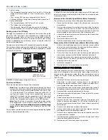
IGNITION CONTROL (P/N 031-01909-000)
Normal flame sense current is approximately
2.4 microamps DC (µa)
Low flame signal control lockout point is
0.15 microamps DC (µa)


