background image

www.yorkfitness.com

www.yorkfitness.com

7

3

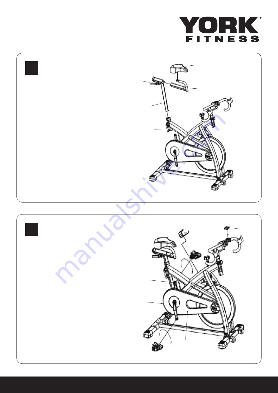
Insert the seat post (42) into the seat tube 

on the frame. Attach the saddle (1) into 

seat slider (41). Make sure the saddle clamp 

screw tighten security. Insert the seat slider 

(41) into the seat post (42) and fix. Using 

release lever (4) adjusts and tightens the 

height in the desired position.

#1

#41

#42

#4

#4

4

Attach the pedals (11) into the crank arms 

(7)(5), each pedal is marked with L (left) or 

R (right) to denote the side of the spinning 

bike they are on. Note - the right hand 

crank is on the same side as the chain 

guard (24). Be careful to align the threads 

correctly to avoid damaging them. Apply-

ing a little grease on the threads will help 

the pedals to screw in easily and correctly, 

tighten using a 15mm spanner; both 

pedals should tighten towards the front of 

the spinning bike.

#58

#24

#11

#7

#5

Summary of Contents for 5000SC

Page 1: ...Owner s Manual 5000SC Indoor Training Cycle Item 53094 www yorkfitness com September 24 2014...

Page 2: ...ls Please take the time to read this owner s manual as it will help you to get the most out of your new exercise equipment For more information visit www yorkfitness com CONTENTS Safety information 03...

Page 3: ...um user weight Never use the equipment in any other manner other than the ways explained in these instructions and any wall chart supplied Injuries to health may result from incorrect or excessive tra...

Page 4: ...Standards EN957 1 10 Class HC AS 4092 1993 SERIAL NO 53094 Product s Name Serial Number This product label is an example only it is not the real product name and serial number of the item you have bo...

Page 5: ...act the retailer for assistance 4 Handlebar and seat adjustment It is important that the handlebar and seat are set at the correct height for your body Ask your instructor for assistance Adjusting the...

Page 6: ...3 by inserting it into the head tube on the frame Use the release lever to adjust and tighten the height to the desired position Attach the racing handlebar 21 on the handlebar upper clamp 45 and hand...

Page 7: ...sition 1 41 42 4 4 4 Attach the pedals 11 into the crank arms 7 5 each pedal is marked with L left or R right to denote the side of the spinning bike they are on Note the right hand crank is on the sa...

Page 8: ...ll clamps adjuster knob adjustment X 11 Check toe straps for signs of wear X 12 Check crank bolts and re tighten X 13 Make sure pedals are screwed In X 14 Check belt tension X 15 Wipe the anti rust oi...

Page 9: ...www yorkfitness com 9 Notes...

Page 10: ...www yorkfitness com 10 1 1 Exploded Drawing...

Page 11: ...GE 1PC 53094 033 31 BRAKE SYSTEM 1SET 53094 034 32 CRANK BOLT 2PCS YORK REF REF DESCRIPTION QTY 53094 035 33 FLYWHEEL SECURITY NUT 2PCS 53094 036 34 OUTER CHAIN GUARD BOLT M6 4PCS 53094 037 35 BOLT AN...

Page 12: ...www yorkfitness com...

Reviews: