YOKOGAWA WE7281 User Manual Download Page 22

2-1

IM 707281-01E

Har

d

ware Preparation

2

Chapter 2  Hardware Preparation

2.1

Installing the Module into the Measuring Station

Preparing to Install the Module

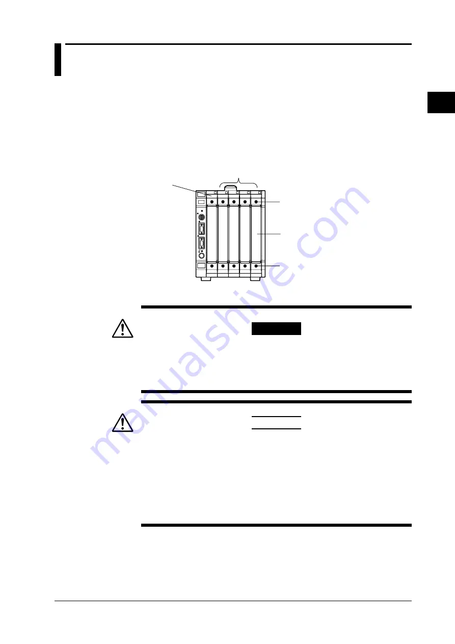
Upon purchasing the measuring station, each slot is covered with a cover plate as shown

in the figure below.  Verify that the power supply is not connected to the measuring

station, then loosen the module attachment screws (2 locations) and remove the cover

plate from the slot where the module is going to be installed.  Please note that the slot on

the left end is dedicated to the communication interface module and this module cannot

be installed there.

* The following figure shows an example of the measuring station WE400.

Slots for other modules

Slot dedicated to 
the communication 
interface module

Module attachment screw

Module attachment screw

Cover plate

Installing the 4-CH, 100 kS/s D/A Module

WARNING

• Make sure to fasten the top and bottom attachment screws. If you connect the

input signal cable without fastening the attachment screws, the protective

grounding  of the measuring station provided by the power cord is compromised

and may cause electric shock.

CAUTION

• To avoid damaging the instrument when installing modules, make sure to turn

OFF the standby power switch of the measuring station.

• Be careful not to get your fingers caught in the ejection lever while inserting the

module.  In addition, do not put your hand inside the slot, because there are

protrusions along the module guide.  You may injure your fingers from them.

• Do not remove the cover plates from unused slots. It can cause overheating and

cause malfunction.  Cover plates are also needed to minimize the influence

caused by electromagnetic interference.

Insert the module along the guide rail of the slot from which you removed the cover plate.

Insert the module until it clicks into the connector.  Be careful not to get your fingers

caught in the ejection lever while inserting the module. When the module is securely

inserted, fasten the module attachment screws (tightening torque: 0.6 to 0.7 N-m).

To remove the module, loosen the module attachment screws, and pull the ejection lever

from the inside to the outside.  This will force the module out of the slot.

Summary of Contents for WE7281

Page 1: ...User s Manual IM 707281 01E 2nd Edition IM 707281 01E 2nd Edition 4 CH 100 kS s D A Module ...

Page 2: ... of this manual describe WE7000 Control Software Ver 4 0 2 0 and module software Ver 3 09 If you are using another version of the software the operating procedures or the figures given in this manual may differ from the actual software The figures of operation panels that are used in this manual correspond to WE7281 If you are using WE7282 WE7282 will be displayed The contents of this manual are s...

Page 3: ...terminals NO When contacting the dealer from which you purchased the instrument please quote the instrument No The following is an example of WE7281 The name plate is also at the same position for WE7282 MODEL MODEL NO NO Made in Japan Standard Accessories The following standard accessories are supplied with the instrument Make sure that all items are present and undamaged User s Manual 1 IM707281...

Page 4: ...ts Conventions Used in This Manual Unit k Denotes 1000 Example 100 kHz K Denotes 1024 Example 720 KB Displayed characters Alphanumeric characters enclosed with usually refer to characters or settings that are displayed on the screen Symbols The following symbol marks are used to attract the operator s attention Affixed to the instrument Indicates danger to personnel or to the instrument The operat...

Page 5: ...4 IM 707281 01E ...

Page 6: ... Hardware Preparation 2 1 Installing the Module into the Measuring Station 2 1 2 2 Connecting the Output Signal Wire 2 3 Chapter 3 Software Operation 3 1 Selecting the Waveform Generation Mode 3 1 3 2 Setting the Output Conditions in the DC Mode 3 2 3 3 Setting the Output Condition in the AG Mode 3 4 3 4 Setting the Output Condition in the FG Mode 3 9 3 5 Turning ON OFF the Output 3 16 Chapter 4 T...

Page 7: ...e cycle of the waveform the address values correspond to the phase angles of the waveform Phase computing unit N Adder Latch Reference clock Waveform memory Waveform output D A LPF Waveform output If N is one input to the adder and the other input is 0 the adder outputs N The latching circuit outputs N in sync with the standard clock This value N will be the first address of the waveform memory Ne...

Page 8: ...ata processor Data processing program memory Isolation D A Programmable LPF ATT Output amp CH1 CH2 CH3 CH4 The data processor on the module creates and processes the waveform data according to instructions from the PC that are received via the WE bus of the measuring station The waveform data passes through the isolator Then they are converted to analog values using the D A converters of each chan...

Page 9: ...No No Frequency amplitude duty Offset voltage No No Yes Phase No No Yes 1 mHz to 20 kHz during sine wave generation The differences between the creation and generation of arbitrary waveforms in the AG mode and in the FG mode are as follows AG mode Used when outputting pattern waveforms The maximum allowable data length is 4 Mwords CH when using 1 CH Data saved by digital oscilloscope and digitizer...

Page 10: ...nuous output Continuously outputs the DC voltage signal at the specified level Output ON OFF 0 V Output voltage Trigger output Outputs the DC voltage signal at the specified level when a trigger occurs Output ON OFF Output voltage Trigger signal 0 V Gate output Outputs the DC voltage signal at the specified level while the gate signal is enabled Output ON OFF Output voltage 0 V Gate signal Note Wh...

Page 11: ...stered in each memory block can be output sequentially every time the trigger occurs You can select the number of partitions from 1 2 4 8 16 32 64 128 and 256 When auto load is used to load waveform data the number of partitions is set to the number of blocks of the waveform data being loaded Setting the data length You can specify the data length of the waveform to be generated The range is from ...

Page 12: ...Output ON OFF Output voltage Trigger signal Start block Start block End block Repeat Continuously outputs the waveform in the specified block when a trigger occurs Output ON OFF Output voltage Trigger signal One block of waveform Note The trigger can be activated by inputting the bus trigger signal or by clicking the ManualTrigger button on the operation panel A trigger signal that is provided via...

Page 13: ...els and blocks in the file at once For wvf files the following settings are also loaded the number of channels the output voltage range of each channel the number of block partitions and the sampling interval For csv files the number of channels used is automatically loaded but the number of block partitions is set to 1 Manual load Loads the data of the specified slot channel and block number Only...

Page 14: ...uty cycle can be generated Inversion Ramp wave The selectable oscillation frequencies range from 1 mHz to 10 kHz Inversion Triangular wave Generates a triangular wave with 50 symmetry The selectable oscillation frequencies range from 1 mHz to 10 kHz Inversion Arbitrary waveform An arbitrary waveform can be generated by loading the arbitrary waveform data data length is fixed to 64 Kwords The selec...

Page 15: ...its of one cycle Note When the output mode is set to Trigger the trigger can be activated by inputting the bus trigger signal or by clicking the Manual Trigger button on the operation panel When the output mode is set to Gate the gate can be opened or closed by inputting the bus trigger signal as a gate signal or by pressing down on the Manual Trigger button on the operation panel for the desired ...

Page 16: ...e ranges see section 5 1 Performance Specifications 0 V Center value Amplitude Offset voltage Phase You can set the initial phase of the oscillation for each channel However if the phase setting is changed after waveform generation is started the actual phase differences between the waveforms of each channel are not necessarily the phase differences that were specified Trigger signal Output wavefo...

Page 17: ...itrary Sweep using an arbitrary pattern Loading the sweep pattern When the sweep pattern is set to Arbitrary an arbitrary pattern is loaded You can load the following files containing data of length 64 Kwords wvf file a corresponding header file with file extension hdr is also needed see page 1 13 ASCII data in csv format see page 1 13 Note If the data length of the file being loaded is greater th...

Page 18: ...gle sweep when a trigger occurs then hold the last value and output a continuous oscillation waveform Trigger signal Start sweep Start sweep Hold the last value Reset to initial value Setting the sweep time Set the time duration for one sweep operation The selectable range is 1 to 1000 s Note Sweep control will be used for trigger input signals if the sweep mode not set to OFF Trigger outputs duri...

Page 19: ...ension hdr Save the waveform data on another module to wvf format or create the data using the Waveform Editor 707751 ASCII data in csv format Create a new ASCII data file in csv format according to the following guideline extract only the waveform data from an ASCII data file in csv format that was saved using another module or a file that was created by using a spread sheet application Column da...

Page 20: ...cal value between the trigger output signal and the bus trigger signal In addition the bus trigger signal can be used as the trigger gate signal during trigger oscillation and gate oscillation operations There is approximately 12 5 µs typical value of delay time from the time the bus trigger signal becomes True to the time the trigger oscillation starts And there is a delay of approximately 12 5 µ...

Page 21: ...k Provides 4 channels of output terminals START OUTPUT H L CH1 H L CH2 H L CH3 H L CH4 10V L TERMINALS CAT BETWEEN CHANNELS 250V MAX 250V MAX to WE7282 START OUTPUT 10V CH1 CH2 CH3 CH4 L TERMINALS 42 4VpkMAX to 42 4VpkMAX CAT 4 CH 100kS s BETWEEN CHANNELS Start indicator Output terminal Lights when the waveform is being output Provides 4 channels of BNC output terminals ...

Page 22: ...nt screws the protective grounding of the measuring station provided by the power cord is compromised and may cause electric shock CAUTION To avoid damaging the instrument when installing modules make sure to turn OFF the standby power switch of the measuring station Be careful not to get your fingers caught in the ejection lever while inserting the module In addition do not put your hand inside t...

Page 23: ... shows an example of WE7281 WE7282 can also be installed or removed in a similar fashion Module attachment screw Module attachment screw When removing the module Ejection lever Note When synchronizing output signals from multiple 4 CH 100 kS s D A modules install the modules in adjacent slots ...

Page 24: ...o not apply a voltage exceeding the following levels as it may damage the module Maximum common mode voltage 250 VACrms or 250 VDC between the ground and the L terminal Maximum voltage between channels 250 VACrms or 250 VDC between terminals of different channels Do not connect to the N C no connection terminals Applying signal to them may damage the module Do not apply external voltage across the...

Page 25: ...is connected to the output terminal isolated BNC on the front panel of the module There are four channels of output terminals CAUTION Do not apply voltages that exceed the following values as it may damage the module Maximum common mode voltage 42 4 VDC ACpeak between the ground and the L terminal Maximum voltage between channels 42 4 VDC ACpeak between terminals of different channels Note The max...

Page 26: ...elect the waveform generation mode Selecting the Waveform Generation Mode Select the mode using the Operation Mode option button The choices are shown below DC is default DC DC output Outputs DC voltage AG Arbitrary waveform output Outputs an arbitrary waveform using waveform data that are loaded FG Function generator output Outputs the selected waveform The selectable waveforms are sine pulse and...

Page 27: ... can be set in units of 0 0001 V in the 1 V range and 0 001 V for all other ranges Setting the Output Mode Select the output mode using the Output Mode option button The choices are shown below Cont is default Cont Continuous output Continuously outputs DC voltage from the time the Output button is clicked to turn the output ON until the next time it is clicked to turn the output OFF Trigger Trigg...

Page 28: ...low is used to set the trigger signal output source channel Trig tab Select the output channel Click the Source button to select the source channel that will be used to output the trigger signal When the output value of the source channel changes the trigger signal is generated 3 2 Setting the Output Conditions in the DC Mode ...

Page 29: ... Shot One Shot Single shot oscillation Outputs the waveform once when the output is turned ON by clicking the Output button Cont Continuous oscillation Continuously outputs the waveform of the block specified by Start Block No from the time the output is turned ON by clicking the Output button until the output is turned OFF by again clicking the Output button Trigger Trigger oscillation After the ...

Page 30: ...length Selecting the time base Select which of the following time bases to use during data output in the Time Base list box Internal Sample the waveform data using the sampling interval based on the module s internal clock BUSCLK Sample the waveform data by synchronizing to the time base signal of the measuring station CMNCLK For setting procedures see section 4 6 Setting the Trigger Source Time B...

Page 31: ...e if the number of blocks is 10 the number of memory partitions is set to 16 Setting the data length Set the data length of the output waveform in the Pattern Length entry box The range is 10 to the maximum allowable data length When auto load is used to load waveform data the data length is automatically set to the data length of each block of the waveform data being loaded Note Data in the memor...

Page 32: ...ly one block can be loaded Manual Load Load the waveform data according to the following procedure 1 Set the number of channels CH Mode and the number of memory partitions Memory Partition of the waveform data to be loaded 2 In the menu that appears by clicking the Manual button select the slot channel number to which the waveform data are to be loaded When the 4 CH 100 kS s D A modules are not li...

Page 33: ...r in a dialog box as shown below Select the channel and block that are to be loaded in the Trace Name and Block No list boxes respectively Select the name of the desired channel Select the desired block number 7 Click the OK button to load the waveform data to the channel that was selected in step 2 Only one block of a channel can be loaded with one operation 3 3 Setting the Output Condition in th...

Page 34: ...e amplitude of the ouput voltage Load arbitrary waveform data Turn ON OFF the waveform output Selecting the Output Channels and Range Select the channel for which to set the output in the CH list box Clicking the On box enables the output Select the range from 1 V 2 V 5 V and 10 V in the Range list box Selecting the Output Waveform Select the output waveform in the Func list box The choices are sh...

Page 35: ...age in the Ampl Start and Ampl End entry boxes Ampl End is set only when sweeping the voltage For the selectable range and resolution see section 5 1 Performance Specifications When the output waveform is set to DC the output voltage is set to the offset voltage as described in the next section The default amplitude is 2 Vp p Setting the Offset Voltage Enter the offset value of the output voltage ...

Page 36: ...n Trigger Trigger oscillation After the Output button is clicked to turn ON the output the waveform is continuously output when a trigger occurs This continues until the output is turned OFF by again clicking the Output button Gate Gate oscillation After the Output button is clicked to turn ON the output the oscillation starts when the gate is enabled When the gate is disabled the oscillation stop...

Page 37: ...pens the Open dialog box Select a file with extension wvf csv or s16 and click the Open button 3 The setup data of the file being loaded appears in a dialog box as shown below Select the channel and block that are to be loaded in the Trace Name and Block No list boxes respectively Select the channel to be loaded Select the block number to be loaded 4 Click the OK button to load the arbitrary wavef...

Page 38: ...he output waveform of the source channel to output the trigger signal The range is 0 to 360 deg Setting the Sweep The Main SlotX and Swp operation panels are used to set the sweep Swp tab Slot tab Select the parameter to sweep Load the sweep pattern Select the sweep mode Select the sweep pattern Set the sweep time Select the channel to sweep Selecting the parameter to sweep Select which parameter ...

Page 39: ... the Sweep Pattern Selecting the channel that will use the sweep Click the channel selection button of the Swp operation panel and in the menu that appears select the channel that will use the sweep pattern Load Load the sweep pattern according to the following procedure 1 Clicking the Load button of the desired parameter Freq Ampl Duty of the Swp operation panel opens the following dialog box Sel...

Page 40: ...ely Single Sweep once in sync with a trigger Single Hold Perform a single sweep when a trigger occurs then hold the last value and output a continuous oscillation waveform Setting the sweep time Set the time duration for one sweep operation in the Sweep Time entry box The range is 1 s to 1000 s in 1 ms steps 3 4 Setting the Output Condition in the FG Mode ...

Page 41: ...e inverted the O mark to the left of the button turns from gray to green and the waveform output is enabled In addition the START indicator on the front panel of the module turns ON Output OFF When the Output button is clicked when a waveform is being generated the black white colors of the Output button return to their original colors the O mark to the left of the button turns from green to gray ...

Page 42: ...t will operate there If it operates in the other slot the measuring station is likely to have malfunctioned If the module is installed correctly and does not operate the connector might be bad or the IC may have malfunctioned In either case contact your nearest YOKOGAWA dealer to have it repaired There is no waveform output Check whether the O indicator on the left of the Output button 3 15 is gre...

Page 43: ... the System menu of the WE7000 Control Software 3 In the Self Test dialog box that appears select the station name and enter the slot number corresponding to the module and click the Execute button Executing is displayed in the result display box Verifying Test Results If a value other than 0 is displayed in the Result display box of the Self Test dialog box the module is probably malfunctioning P...

Page 44: ...ce Maintenance of Parts There are no parts in this module that require periodic replacement Calibration We recommend that you calibrate the measurement module once a year to assure its accuracy Please contact your nearest YOKOGAWA dealer to have the module calibrated ...

Page 45: ... C 10 V 1 mV 0 05 of setting 4 mV 50 ppm of setting 220 µV C Settling time 32 µs until the value settles within 0 1 of the final value typical vlaue Trigger source Manual bus trigger signal BUSTRG1 BUSTRG2 of the measuring station During Function Waveform FG Output Output waveform Sine pulse variable duty cycle ramp triangular arbitrary and DC Output frequency range and resolution 1 mHz to 20 kHz ...

Page 46: ...90 typical value 2 Overshoot Less than or equal to 0 5 of the output p p value typical value 2 Output jitter 5 µs Duty cycle setting Range 0 to 100 resolution 0 1 Time accurcary 0 01 of 1 the output frequency 5 µs Phase Target Start and stop phase of trigger oscillation gate oscillation and continuous oscillation Range 360 Resolution 0 1 Output operation Continuous trigger and gate Trigger source ...

Page 47: ... the number of memory paritions Waveform output mode Single continuous single by triggering and continuous by triggering Trigger source Manual bus trigger signal BUSTRG1 BUSTRG2 of the measuring station Bus trigger output Output at an arbitrary sample of the specified channel Bus trigger output time accuracty sampling interval 7 5 µs Synchronized Operation Skew between channels Within the same mod...

Page 48: ...s µs Memory Partition 1 Start Block No 1 Stop Block No 1 Output Off Trigger Out Point 1 Auto On CH MODE 4ch Time Base Internal Manual CH1 of its own module Block No 1 Operation Mode During FG Mode Cont CH1 to CH4 Off Range 1 V Function Sine Freq Start 1000 Hz Freq End 1000 Hz Ampl Start 2 Vp p Ampl End 2 Vp p Offset 0 V Phase 0 Duty Start 50 0 Duty End 50 0 Delay 0 V Invert Off Trigger Out Source ...

Page 49: ...d Warm up Time At least 30 minutes Maximum Common Mode Voltage between L Terminal and Ground WE7281 250 VDC or 250 VACrms WE7282 42 4 VDC ACpeak Maximum Voltage between Channels WE7281 250 VDC or 250 VACrms WE7282 42 4 VDC ACpeak Withstand Voltage Between output terminal and ground WE7281 WE7282 1500 VACrms at 60 Hz for one minute Between channels WE7281 2300 VACrms at 60 Hz for one minute WE7282 ...

Page 50: ... with electricity from a circuit containing an overvoltage control device Overvoltage Category II Applies to equipment supplied with electricity from fixed installations like a distribution board 2 Pollution Degree Applies to the degree of adhesion of a solid liquid or gas which deteriorates withstand voltage or surface resistivity Pollution Degree 1 Applies to closed atmospheres with no or only d...

Page 51: ...4 CH 100kS s D A Module WE7281 33 242 4 227 4 5 START OUTPUT H L CH1 H L CH2 H L CH3 H L CH4 10V L TERMINALS CAT BETWEEN CHANNELS 250V MAX 250V MAX to WE7282 33 242 4 227 4 5 If not specified the tolerance is 3 However in cases of less than 10 mm the tolerance is 0 3 mm ...

Page 52: ...1 5 3 6 MODEL 2 N NO 2 O Offset 3 10 Offset voltage setting 3 10 One Shot 1 6 3 4 Operation Mode 3 1 Operation principle 1 1 Output button 3 16 Output entry box 3 2 Output frequency 1 10 Output frequency setting 3 10 Output Mode 1 4 Output Mode AG 3 4 Output Mode DC 3 2 Output Mode FG 3 11 Output ON OFF 3 16 Output timing 3 5 3 13 Output waveform selecting 3 9 P Package 2 Phase 1 10 3 10 Pin arran...

Reviews: