6-6
IM DR231-01E
6.3
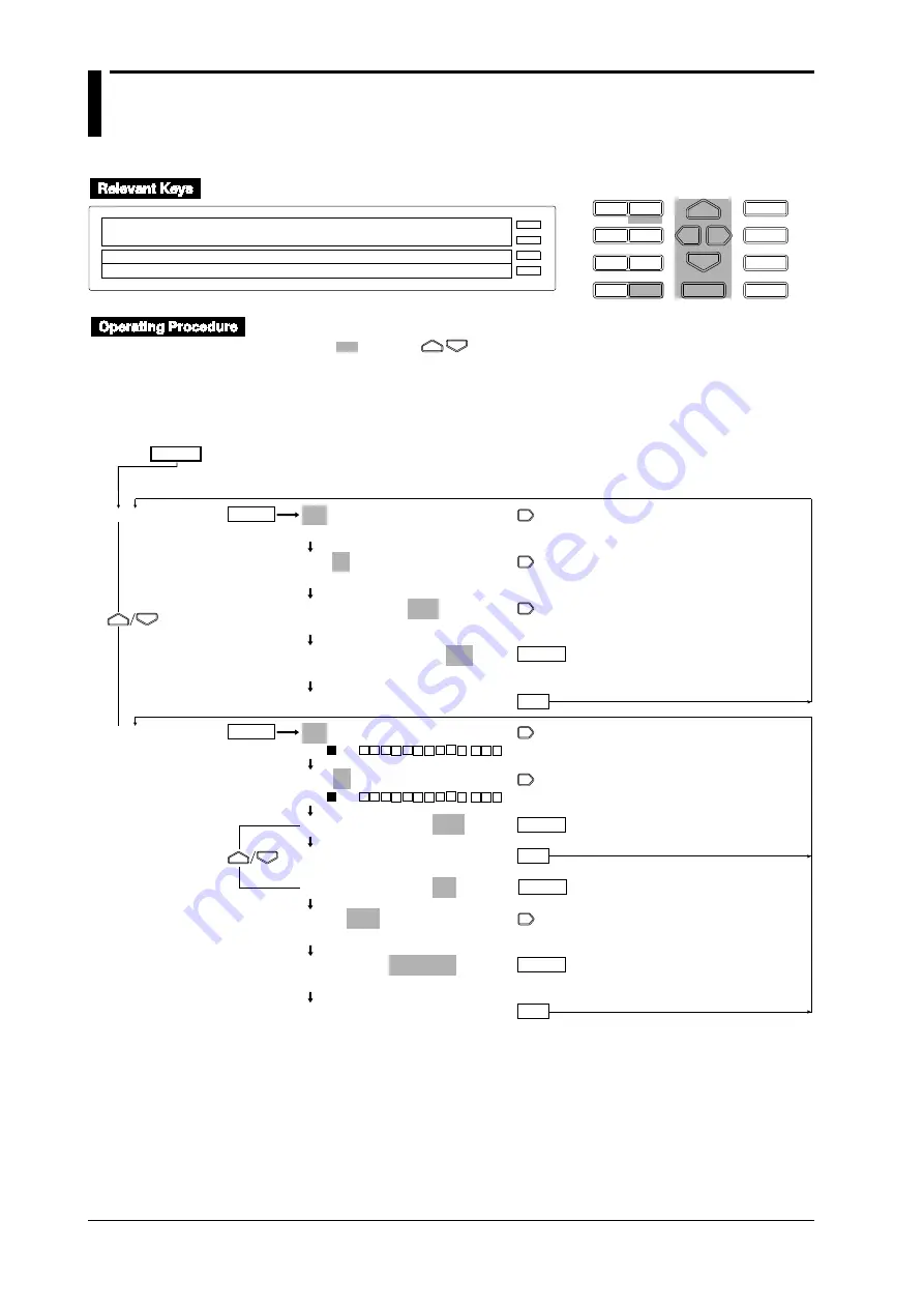
Setting Recording Zones and Partially
Expanded Recording
D I S P
M O D E
P R I N T
F U N C
I N S
D E L
R A N G E A L A R M
S E T
C H A R T
E N T E R
F E E D
M. F U N C 1
M. F U N C 2
RECORD
ALARM
CHART
KEYLOCK
R E C O R D
SET=ZONE
CHART2 ZONE PARTIAL TAG DIGITAL_PR MAN
↑
>Select Setting Parameter
E S C
• Press the SET key for three seconds to enter the SET3 menu.
• Select/set
using the
keys.
• To escape from a lower menu, press the MODE (ESC) key. Its main menu will appear,
although new settings/selections will not be kept.
• New settings/selections will be kept when you reach the final display of that setting.
SET=
ZONE
PARTIAL
001-01:ZONE=_ _0~250mm
*1
>Select Channel No.
001-01:ZONE=_ _0~250mm
*1
>Select Channel No.
001-01:ZONE=_ _0~250mm
*1
>Left limit(0~245mm)
*2
001-01:ZONE=_ _0~250mm
*1
>Right limit(5~250mm)
*3
***SET OK***
001-01:PARTIAL=OFF
>ON 001 - - -
001-01:PARTIAL=OFF
>ON 001 - - -
001-01:PARTIAL=OFF
***SET OK***
001-01:PARTIAL=ON
RATE 50%=_0.0000V
>Rate Limit(1~99%)
RATE 50%=_0.0000V
>Boundary Limit(–1.9999~1.9999V)
***SET OK***
ENTER
ENTER
ENTER
ENTER
ESC
ESC
ENTER
ENTER
ESC
(Main menu)
(Lower menu)
*1: For Model DR130, indicated as "001-01 : ZONE = _ _0-150 mm."
*2: For Model DR130, indicated as "> Left limit (0-145 mm)."
*3: For Model DR130, indicated as "> Right limit (5-150 mm)."
Summary of Contents for DR231
Page 12: ...10 IM DR231 01E...


