6-15
IM 2560A-01EN
Temperature-Sensor-Simulation Thermoelectromotive-Force and Resistance Sourcing
3
2
1
4
5
6
7
8
9
10
11
12
13
14
15
16
App
Index
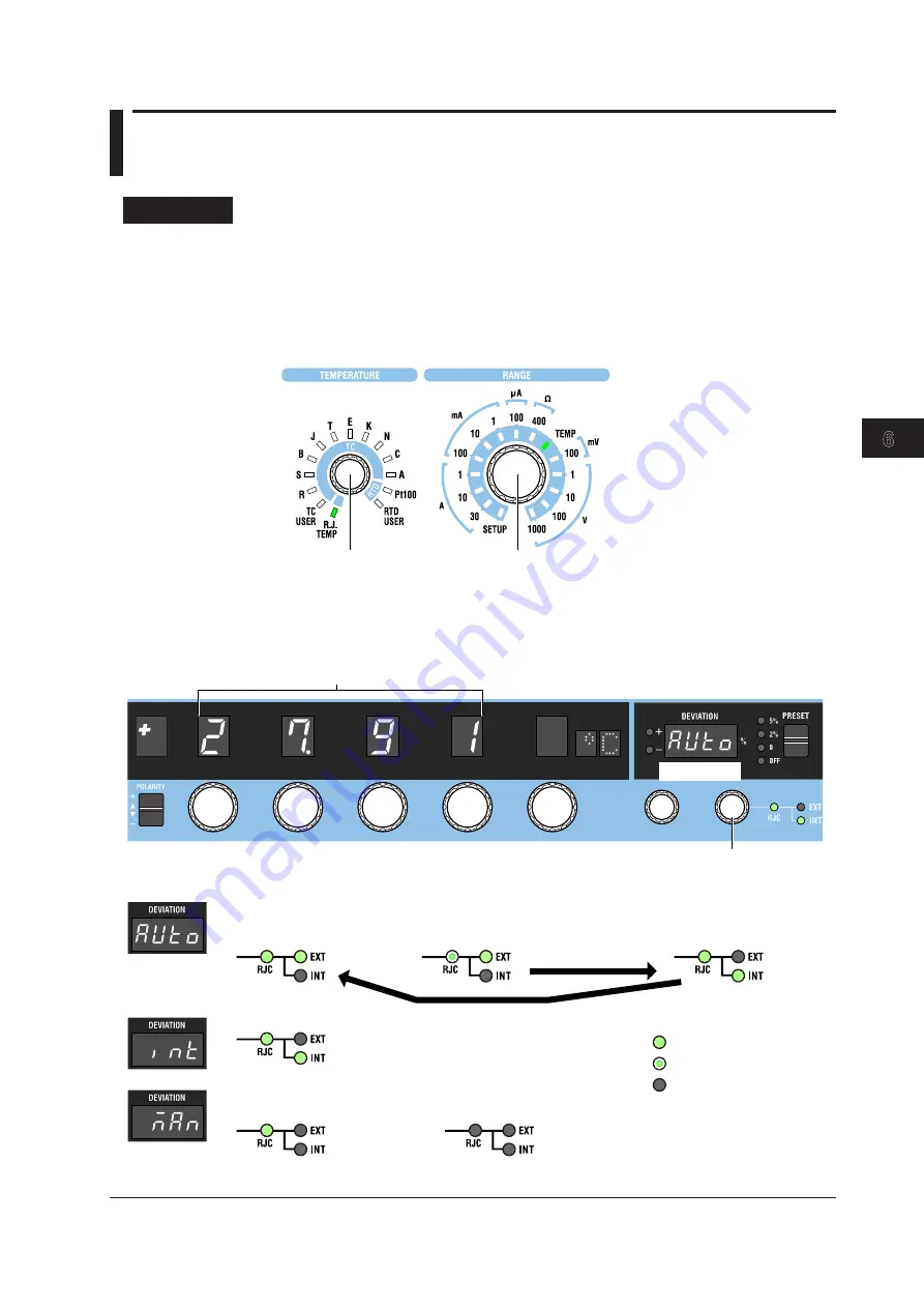
6.6 Setting Reference Junction Compensation
Procedure
1
.
Turn the
RANGE
dial to select TEMP.
The TEMP indicator illuminates, and the TEMPERATURE dial is enabled.
2.
Turn the
TEMPERATURE
dial to select R.J. TEMP.
• The R.J. TEMP indicator turns on.
• The displayed unit will be °C.
RANGE dial
TEMPERATURE dial
1. Select TEMP.
The TEMP indicator turns on.
2. Select R.J. TEMP.
The R.J. TEMP indicator turns on.
Setting the Reference Junction Compensation Mode
3.
Turn the
Deviation dial 1
to set the RJC mode to AUTO, INT, or MAN.
The main setting display shows the selected reference junction temperature.
Reference junction temperature
Deviation dial 2
3. Select AUTO, INT, or MAN.
RJC menu
RJC menu
Auto
Internal
Manual input
When the setting is not 0.00°C
When the setting is 0.00°C
When an external RJ
sensor is connected
When an external RJ sensor is not connected
: Off
: On
: Blinking
Internal RJC is applied.
After several seconds
When an external RJ sensor is connected and the 2560A has detected it


