Yeasn YPB-2100 User Manual Download Page 29


- 25 - 


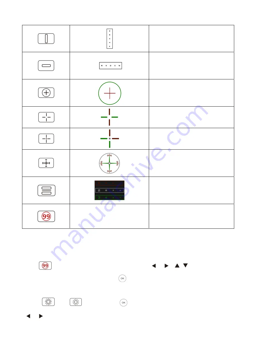
Vertical line optotypes, used for 
detecting horizontal heterophoria 


Horizontal line optotypes, used for 
detecting vertical heterophoria 


Cross ring optotype, used for detecting 
heterophoria 


Cross view optotype ,used for the 
detection of heterophoria. 


cross fixed view optotype ,used for the 
detection of heterophoria. 


Clock disc optotype, used for the 
detection of rotating heterophoria 


Red and green binocular balanced 
optotype, used for the detection of 
binocular balance 


Ishihara 

(indcluding traffic light) 

Ishihara

used for the detection of 

parachromatoblepsia 


Remarks: 

1. Ishihara Chart


Press 

 key, the color blindness will pop-up. Press


key to shift among 

different color blindness visual charts. Press 

  key, shows the test result. 

2. Astigmatic disc chart (two options) 

Press  

  or 

and then Press 

 key, display red indicating visual chart. Press

  to adjust the location of red indicating visual chart. 

Summary of Contents for YPB-2100

Page 1: ...YPB 2100 LCD VISUAL CHART User Manual Version 1 4 Revision date 2022 12...

Page 2: ...do manual do usu rio www yeasn com en Manual de usuario Enlace de descarga www yeasn com en Kullan m K lavuzu ndirme linki www yeasn com en Manuale d uso Link per il download www yeasn com en Link zu...

Page 3: ...rmation in promotional materials and packing boxes is subject to changes due to performance improvement without additional notice Chongqing Yeasn Science Technology Co Ltd reserves the rights to updat...

Page 4: ...Device Startup and Shutdown 17 6 2 How to use the Remote Controller 20 6 3 Other operating instructions 28 7 Troubleshooting 29 8 Cleaning and Protection 30 8 1 Clean LCD displayer 30 8 2 Clean exter...

Page 5: ...tificate for optometry and glasses If cleaning and maintenance needed please power off the product and unplug from the socket Detailed cleaning and maintenance method please refer to 8 Cleaning and Pr...

Page 6: ...50 20 50 0 5 0 4 4 8 0 2 0 6 0 8 20 40 20 40 0 63 0 5 4 9 0 1 0 8 0 9 20 30 20 30 0 8 0 66 5 0 1 1 20 25 20 25 1 0 8 5 1 0 1 1 2 1 2 20 20 20 20 1 25 1 5 2 0 2 1 5 1 5 20 15 20 15 1 6 1 33 5 3 0 3 2...

Page 7: ...man Serial numb Country of m CE marking Paramet AC 100 50 60 Hz 1 0 0 5A ize ut 4 65 kg controller a 6 mm L controller 1 ecifications nd indicat ations are pa is not paste s er nufacture ber manufact...

Page 8: ...nual booklet Authorized European representative Catalogue number Unique Device Identifier Model number G W Gross Weight DIM Dimension Attention Please refer to accompanying documents Power switch iden...

Page 9: ...y When mounting the device on the wall make sure the wall is able to withstand the weight of 8 kg When mounting the device on the wall reserve a gap over 50mm all around the device The device is hung...

Page 10: ...ains a wireless module and the wireless parameter specifications are as follows transmit and receive Network conditions CS structure local area network mode Modulation type 802 11b CCK 802 11g OFDM 80...

Page 11: ...the limits for a Class B digital device pursuant to Part 15 of the FCC Rules These limits are designed to provide reasonable protection against harmful interference in a residential installation This...

Page 12: ...ont diagram of the displayer host Back diagram of the displayer host 1 LCD displayer 2 Signal receive port 3 Power indicator 4 Power switch 9 Rack mounting hole 8 DC DC socket 5 Label 7 Audio Output J...

Page 13: ...witch of the LCD visual chart 5 Label Product label 6 2 USB 2 0 Ports out put 5V0 5A Can carry out program upgrading video and image play through USB flash disk 7 Audio Output Jack Area Connect to spe...

Page 14: ...Back diagram of the remote controller 1 Label Remote controller label 2 Switch Remote controller switch 3 Battery case Install two AAA grade alkaline batteries 4 Battery cover 1 Label 3 Battery case...

Page 15: ...nect to the AC interface 3 DC output plug Used to connect the monitor DC DC socket 4 Nameplate The nameplate of the power adapter 5 Power adapter indicator When the adapter is connected the work indic...

Page 16: ...6 Wall bearing 1 Pc 7 Remote controller 1 Pc 8 Red and green glasses 1 Pc 9 Hex wrench 1 Pc 10 Power adaptor 1 Pc 11 Adaptor Rack 1 Pc 12 Plain washer grade A 6 2 Pcs 13 Plastic expansion tube M8 38...

Page 17: ...the wall The hole diameter is 8mm and the depth is 40mm The relative positions of the mounting holes are consistent with the 4 small holes with a diameter of 6mm on the wall mount Put 4 M8 38 plastic...

Page 18: ...s 10mm and the relative position of the mounting holes is consistent with the 4 small holes with a diameter of 6mm on the wall mount Flatten the expanded parts of the 4 M10 50 aircraft butterfly plast...

Page 19: ...ing holes Using the screwdriver to screw into the four mounting holes on the monitor Before locking the screws through the two mounting holes on the upper end of the rack first align and align the two...

Page 20: ...age requirements The hanger can adjust the pitch and left and right directions When adjusting the angle pay attention to use both hands to grasp the edge of the display for adjustment Keep a clearance...

Page 21: ...ark is the same as the icon displayed on the remote control button 5 3 Inspection cycle before use every day 6 Directions for Use 6 1 Device Startup and Shutdown 6 1 1 Device startup 6 1 1 1 Turn on t...

Page 22: ...nal Test including Contrast sensitivity Function Structure of Eye and Vision CSF Test 1 Select the contrast sensitivity functional CSF and press the OK button to enter the test interface 2 Start the m...

Page 23: ...Press any key except device power on off button on the controller to light up the displayer and enter working state 6 1 3 Device shutdown Press button on the remote or power on off button on the devi...

Page 24: ...2 How to use the Remote Controller 6 2 1 Remote controller 6 2 2 About the battery in the remote controller Two AAA before use Take out these batteries if the device will not be used for a period of...

Page 25: ...hen automatically enter the setup mode of channel Continuously press 3 seconds and visual chart will be set as channel 1 Continuously press 3 seconds and visual chart will be set as channel 2 Continuo...

Page 26: ...irmation 2 Color blind test display answer 3 Astigmatic disc mark display red dot mark Row display key Press this key to shift between row charts and all charts press once to display row chart press a...

Page 27: ...ptotype 6 2 6 Optotype key introduction Remote control key icon Chart types display of YPB 2100 visual chart Function visual chart display E chart E chart used for visual acuity test of adults and chi...

Page 28: ...vision s grid optoty rical vision h 4 point cting bino al function o optotype ction ion point ction of hete zontal alignm etecting ani ikonia cal alignme cting anisoph ikonia unction matic disc axis a...

Page 29: ...or the detection of rotating heterophoria Red and green binocular balanced optotype used for the detection of binocular balance Ishihara indcluding traffic light Ishihara used for the detection of par...

Page 30: ...lay b Spacing Small Medium Large Factory default Medium c Arrange Regular V Type Factory default Regular d Unit background White Black Factory default White e Scrolling By page By line Factory default...

Page 31: ...Imperial 2 Imperial 3 LogMAR1 LogMAR2 LogMAR3 VAR1 VAR2 VAR3 Set vision value display method Factory default decimal1 6 Scale Red green mark Isometry Retain Factory default Retain Dot mark Isometry R...

Page 32: ...eyes durin our short lin 9 and the ey o be the clos f each line i etween the etween the etween the etween the ctory defaul on ctions ype ng detection nes bulge ou yes It seems sest is as follow short...

Page 33: ...Co Ltd Maintenance Department or the authorized dealer Trouble Reasons Solutions Displayer is not bright The power cord is not correctly connected to the socket Connect the power cord correctly Visual...

Page 34: ...ctric shock Attention Do not wipe the LCD screen with stiff cloth or paper otherwise it may scratch the screen Attention Make sure not to leave water drop on the LCD screen if there is a water drop pl...

Page 35: ...polarity mark and in the battery case Otherwise the remote controller will not work moreover the controller may not work due to battery leakage Attention Please dispose of the used battery properly t...

Page 36: ...Disposal and Environmental protection INFORMATION FOR USERS Please recycle or properly dispose of the used batteries and other wastes to protect the environment This product bears the selective sorti...

Page 37: ...legislation currently in force 12 Manufacturer s Responsibility The company is responsible for the safety reliability and performance impact under below circumstances Assembly addition modifications...

Page 38: ...34 13 Electrical Schematic Diagram For further information and services or any questions please contact with the authorized dealer or manufacturer We will be happy to help you...

Page 39: ...l operation in the configuration in which it will be used Guidance and manufacture s declaration electromagnetic emission The YPB 2100 is intended for use in the electromagnetic environment specified...

Page 40: ...ine s to earth 1 kV differential mode Mains power quality should be that of a typical commercial or hospital environment Voltage dips short interruptions and voltage variations on power supply input l...

Page 41: ...mpliance level in each frequency range b Interference may occur in the vicinity of equipment marked with the following symbol Radiated RF IEC 61000 4 3 3 V m 80 MHz to 2 5 GHz 3 V m NOTE 1 At 80 MHz a...

Page 42: ...W Separation distance according to frequency of transmitter m 150 KHz to 80 MHz 80 MHz to 800 MHz 800 MHz to 2 5 GHz 0 01 0 12 0 12 0 23 0 1 0 38 0 38 0 73 1 1 2 1 2 2 3 10 3 8 3 8 7 3 100 12 12 23 F...

Reviews: