background image

WFC- SC(H) Series 

.

Installation


- 10 - 

 
A  balance  valve  should  be  installed  in  the  chilled-hot  water  outlet  and  a  stop  valve 
should be installed in the chilled-hot water inlet. Both valves along with thermometer 
wells should be placed in close proximity to the chiller-heater, refer figure 12. 
 
After  thoroughly  testing  for  leaks,  insulate  the  piping  circuit  ensuring  an  adequate 
vapor  barrier  is  obtained.  Be  sure  the  insulation  allows  proper  access  to  all 
thermometer wells and hand valves. Be also sure that the chiller-heater panels are not 
restricted by the insulation. 
 
If the equipment is installed outdoors and subject to freezing ambient conditions, trace 
heating  of  the  pipes  under  the  insulation  may  be  considered.  If  glycol  solutions  are 
contemplated,  it  is  important  that  inhibitors  are  in  solution  to  protect  copper  tubes 
internal  to  the  machine.  It  is  further  most  important  to  understand  that  cooling 
capacity  of  the  chiller-heater  will  be  degraded  as  concentrations  of  the  glycol 
solutions increase – it must be noted that there is limited flow rate increase allowance 
for the chilled- hot water circuit. 
 

4.3


 Cooling Water Piping 

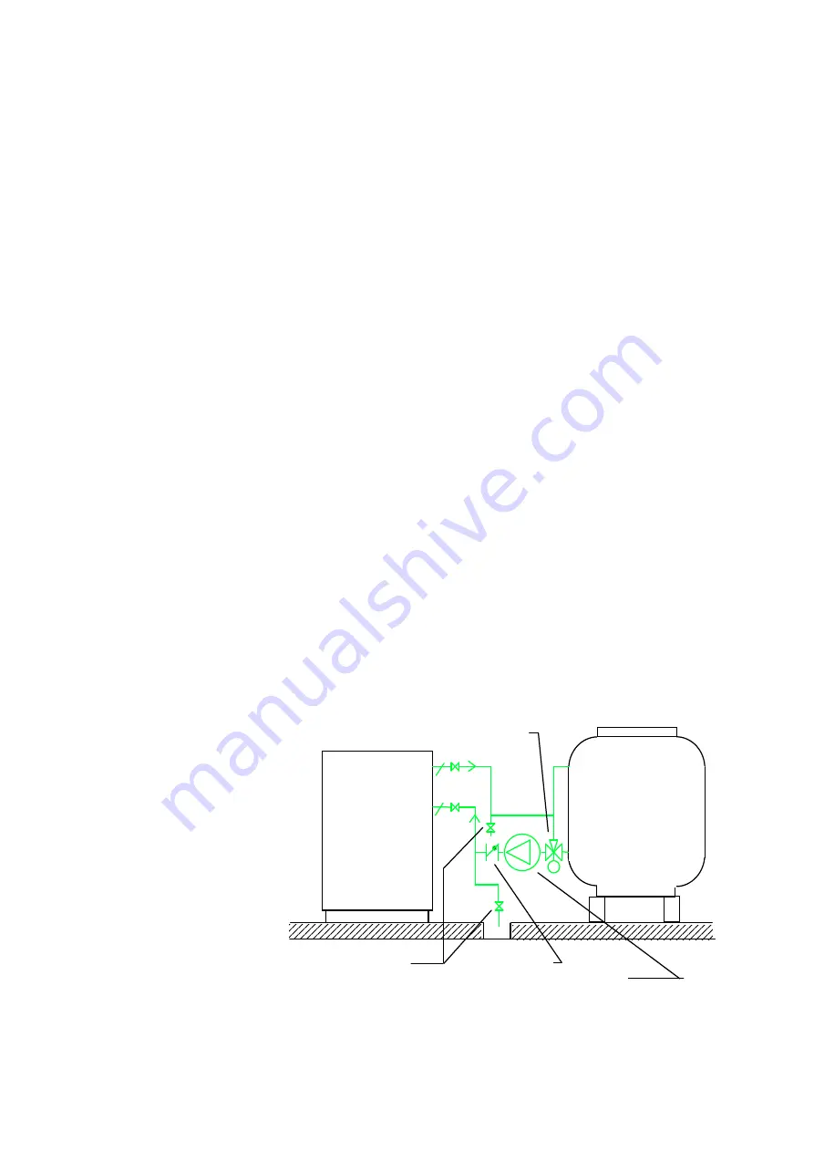
Cooling water to the absorption chiller-heater is required at a temperature of 31°C or 
less during cooling operation. It is also imperative that cooling water less than 24°C 
should  not  be  supplied  to  the  chiller-heater  for  prolonged  periods.(longer  than  30 
minutes).  If  such  contingency  is  likely  to  occur,  a  mixing  valve  facility  must  be 
installed as illustrated in figure 13.  
 
It  is  also  of  particular  importance  to  observe  that  the  cooling  flows  in  a  parallel 
fashion  through  the  WFC-SHC20  &  SCH30  machines  –  dissimilar  to  the  WFC-
SCH10 which flows in parallel. Attention must be paid to the instruction label on the 
machine with respect to the sizing of the transfer pipe on the cooling water inlet. 


Wherever  possible,  install  the  cooling  tower  at  the  same  level  or  higher  than  the 
chiller-heater.  If  it  is  not  possible,  give  careful  consideration  to  the  prevention  of 
drain-back  and  loss  of 
cooling  water  due  to 
overflow  at  the  tower. 
Such  matters  should 
have  been  given  prior 
consideration  by  the 
design  engineer  along 
with  proper  facility  to 
prevent  damage  to  the 
cooling 

tower 

fill 

media  as  a  result  of 
daily,  frequent  mode 
change-over  of  the 
chiller-heater.   


F

   Figure 13 


Chiller-

Heater

Cooling

Tower

Mixing valve

Check valve

Cooling water
pump

Drain valves

Summary of Contents for WFC-SC Series

Page 1: ...WFC SC H Chiller Chiller Heater 2 Installation WFC SC H 10 20 30 50 Version 11 1...

Page 2: ...Electrical Wiring 5 1 Electrical system diagram 12 5 2 Electrical connection of auxiliary equipment 12 5 3 Junction box electrical wiring 13 5 3 1 Location of Junction box 13 5 3 2 Inside of Junction...

Page 3: ...impact 3 Do not attempt to start the system without supervision from a Yazaki authorized service agent 1 2 Receiving When the absorption chiller heater is delivered to site inspect it for transit dam...

Page 4: ...possible to use a crane for lifting a fork lift truck may be utilized In the event a crane or forklift cannot be used and the machine must be manhandled into position minimum dimensions for maneuver...

Page 5: ...f the recommended service clearances cannot be provided as indicated the chiller heater should not be installed Figure 3 Table of Clearances Installation Area Maintenance Clearances Model WFC SC H A B...

Page 6: ...distribution of working fluids internal to the machine to be impaired poor cooling performance will result 3 4 Placement For SC H 10 20 30 When the chiller heater is finally positioned on its foundati...

Page 7: ...indicated in figure 9 to obtain longitudinal and transverse level Should the installation comprise more than one chiller heater located side by side it is important that all machines be individually l...

Page 8: ...er temperatures during commissioning and maintenance procedures All piping should be properly aligned and graded to a drain valve to permit complete drainage of the system Properly located air vents s...

Page 9: ...7 Do not exceed 588 kPa in the water heat medium circuit Figure 10 Typical piping system diagram WFC SC20 SH20 WFC SC30 SH30 WFC SC50 WFC SC10 SH10 Cooling Tower P P P P P P Air vent Air vent Drain Ch...

Page 10: ...it install purge valves to expel trapped air Valve Thermometer Wells Chiller Heater Chiller Heater Chilled hot water pump Fan coil Fan coil Expansion tank Closed System Open System Water supply Cister...

Page 11: ...ater circuit 4 3 Cooling Water Piping Cooling water to the absorption chiller heater is required at a temperature of 31 C or less during cooling operation It is also imperative that cooling water less...

Page 12: ...eater warranty 4 4 Heat Medium Piping The heat medium pipe work will most likely be a closed system Accordingly since temperature of the heat medium may operate as high as 95 C with a standard inlet 8...

Page 13: ...ote 4 Connect to Junction Box Note 5 In case of using 3 wayvalve Note 6 CTS P3A RT1 CM1 3 3way valve RT1 THR1 P SW1 RT2 THR2 CP SW2 RTF THRF SWF RT3 THR3 P3A SW3 RT3 LMT1 SWV RTV Do not exceed 24VAC 6...

Page 14: ...cation of Junction box Junction box is located left bottom of the Chiller refer to figure 5 3 1a WFC SC H 10 20 30 WFC SC50 Junction box is located rear bottom of the Chiller refer to figure 5 3 1b Fi...

Page 15: ...ing water pump 4 Error signal from cooling water pump 5 Error signal from cooling tower fan 6 Error signal from heat medium pump 7 Not Use 8 Not Use CM2 Error signals common circuit S3 S4 Requirement...

Page 16: ...ote switch Connect the dry contact signal according to Figure 5 4 2 Take off the 2 screw to open the cover Take off the front panel CB Figure 5 4 1 Control panel Attention You must not give any voltag...

Page 17: ...WFC SC H Series Installation 16 5 4 3 Position of RUN REMOTE STOP Switch Adjust the Run Remote Stop switch to the position of the Remote RUN REMOTE STOP Switch Figure 5 4 3 Control Panel...

Page 18: ...B Figure 5 5 1 typical connection L1 L2 L3 U V W TR1 TR3 TR14TR5 TR6 TR7 TR8 15 16 17 18 S14 S13 S12 S11 TR9TR10TR11TR12TR13 S1 S2 S5 S6 S8 S9 S10 R1 24VAC L1 L2 R2 R1 R2 GL RL Terminal marking Descri...

Page 19: ...th substantial bleed off would be necessary to achieve this result in the cooling water circuit If such water quality in supply is not available under all circumstances chemical treatment is required...

Page 20: ...ler heater has been installed piped flushed leak tested and electrically wired as described in these instructions and in full compliance with all pertinent safety codes the Yazaki authorized distribut...

Page 21: ...ipes 13 Make up and fill lines installed to the cooling tower and chilled hot water circuit 14 Air vent valves correctly installed 15 All water pipes cleaned flushed filled and leak tested ready for o...

Reviews: