


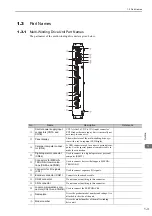


1 Outline
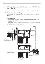
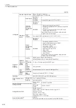
1.4.2 Basic Specifications
1-10
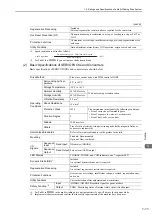
I/O Signals
Encoder Output Pulses
Phases A, B, and C: Line driver
Encoder output pulses: User specified.
Sequence
Inputs
Fixed Inputs
Number of
Channels
3
Functions
External latch signals (/EXT1 to /EXT3)
Input Sig-
nals That
Can Be Allo-
cated
Number of
Channels
7
Functions
• Homing deceleration switch (/DEC)
• Forward run prohibited (P-OT) and reverse run prohib-
ited (N-OT)
• Forward external torque limit (/P-CL) and reverse
external torque limit (/N-CL)
Signal allocations can be performed, and positive and
negative logic can be changed.
Fixed
Outputs
Servo alarm (ALM) and alarm code (ALO1, ALO2, ALO3)
Output
Signals That
Can Be
Allocated
Number of
Channels
3
Functions
• Positioning completion (/COIN)
• Speed coincidence detection (/V-CMP)
• Rotation detection (/TGON)
• Servo ready (/S-RDY)
• Torque limit detection (/CLT)
• Speed limit detection (/VLT)
• Brake (/BK)
• Warning (/WARN)
• Near (/NEAR)
Signal allocations can be performed, and positive and
negative logic can be changed.
Communi-
cations
Function
RS422A
Communi-
cations
(CN54)
Interface
Digital operator (Model: JUSP-OP05A-E),
personal computer (can be connected with S)
1:N
Communica-
tions
N = Up to 15 stations possible at RS422A port
Axis
Address
Setting
Set by parameter
USB
Communi-
cations
(CN4)
Interface
Personal computer (can be connected with S)
Communica-
tions
Standard
Complies with standard USB 1.1. (12 Mbps).
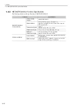
Indicators
MS1, MN1, MN2, MN3, and MN4 LED indicators
Panel Operator Func-
tions
Display Unit
Five, 7-segment LED digits
Switches
Four push switches
MECHATROLINK-II Communications
Setting Switches
Rotary Switch
(S1001)
Positions: 16 positions
DIP Switch
(S1002)
Number of pins: 4
Analog Monitor (CN1)
Number of points: 2
Output voltage:
±
10 VDC (linearity effective range:
±
8 V)
Resolution: 16 bits
Accuracy:
±
20 mV (Typ)
Max. output current:
±
10 mA
Settling time (
±
1%): 1.2 ms (Typ)
Dynamic Brake (DB)
*2
Included.
External dynamic brake units are required for the SERVOPACKs.
(cont’d)