


9 Appendix
9.1.2 Parameters
9-22
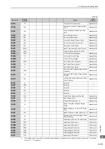
Pn561
2
Overshoot Detection Level
0 to 100
1%
100
Immediately
Setup
5.2.1
Pn600
2
Regenerative Resistor Capacity
*2
Depends on
SERVO-
PACK
Capacity
*3
10 W
0
After restart
Setup
3.9.3
Pn601
2
Dynamic Brake Resistor Capacity
0 or higher
(Max. value
depends on
model.)
*3
10 W
0
After restart
Setup
3.10.2
Pn800
2
Communications Control
–
–
0040
Immediately
Setup
*1
∗1.
For details, refer to the
Σ
-V Series/DC Power Input
Σ
-V Series/
Σ
-V Series for Large-Capacity Models User’s Man-
ual MECHATROLINK-II Commands
(Manual No.: SIEP S800000 54).
∗2.
Normally set to "0." When using an external regenerative resistor, set the capacity (W) of the regenerative resistor
unit.
∗3.
The upper limit is the maximum output capacity (W) of the SERVOPACK.
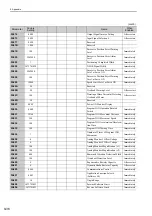
(cont’d)
Parameter
No.
Size
Name
Setting
Range
Units
Factory
Setting
When
Enabled
Classi-
fication
Reference
Section
MECHATROLINK-
II
Communications Check Mask (for debug)
0
No mask
1
Ignores MECHATROLINK communications error (A.E6
).
2
Ignores WDT error (A.E5
).
3
Ignores both MECHATROLINK communications error (A.E6
) and WDT error (A.E5
).
Warning Check Mask
0
No mask
1
Ignores data setting warning (A.94
).
2
Ignores command warning (A.95
).
3
Ignores both data setting warning (A.94
) and command warning (A.95
).
4
Ignores communications warning (A.96
).
5
Ignores both data setting warning (A.94
) and communications warning (A.96
).
6
Ignores both command warning (A.95
) and communications warning (A.96
).
7
Ignores data setting warning (A.94
), command warning (A.95
) and communications warning
(A.96
).
Reserved (Do not change.)
Reserved (Do not change.)
4th 3rd 2nd 1st
digit digit digit digit
n.