


7 Monitor Displays (Un
)
7.5.1 Interpreting Safety Input Signal Display Status
7-6
7.5
Monitoring Safety Input Signals
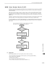
The status of safety input signals can be checked with the safety I/O signal monitor (Un015). The procedure
for the method of interpreting the display and a display example are shown below.
7.5.1
Interpreting Safety Input Signal Display Status
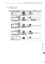
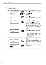
The safety I/O signal monitor (Un015) can be read in the following way. The upper level indicates ON, and
the lower level indicates OFF. All undefined digits are shown in the lower level (OFF).
Note: Input signals use the following circuit configuration.
• OFF: Open
• ON: Short-circuited
Example
7.5.2
Safety Input Signal Display Example
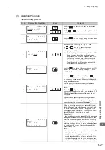
Safety input signals are displayed as shown below.
• When the /HWBB1 signal turns OFF to activate the HWBB function
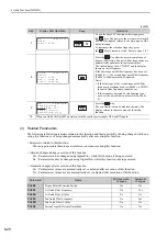
Display LED Number
Input Terminal Name
Signal Name
1
CN8-3, -4
/HWBB1
2
CN8-5, -6
/HWBB2
3
−
Reserved
4
−
Reserved
5
−
Reserved
6
−
Reserved
7
−
Reserved
8
−
Reserved
U n 0 1 5 =
8 7 6 5 4 3 2 1 digit
MECHA
ON (short-circuited)
U n 0 1 5 =
8 7 6 5 4 3 2 1 digit
The first digit is
in the lower level.
MECHA


