background image

www.dadehpardazan.ir 88594014-15

3  Wiring and Connection

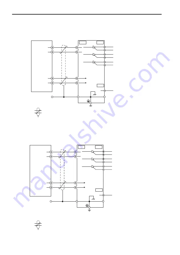
3.5.2  Linear Scale Connection Examples

3-44

(3)

Linear Scale Made by Mitutoyo

 represents shielded twisted-pair wires.

(4)

Linear Scale Made by Magnescale Co., Ltd.

SR75, SR85, SR77, SR87

 represents shielded twisted-pair wires.

Absolute linear scale

made by Mitutoyo

PS

/PS

PG5V

PG0V

2

6

1

5

Shielded wire

Connector

shell

PG5 V

PG0 V

5

6

1

2

Connector

shell

SERVOPACK

CN2

CN1

19

0 V

PAO

/PAO

PBO

/PBO

PCO

/PCO

17
18

20

21
22

Connector

shell

Phase A

Phase B

Phase C

Output line-driver 

SN75ALS194 manu-

factured by Texas

Instrument or the 

equivalent

CN1

SG

16

JZSP-CLP70-

-E

Linear scale made by

Magnescale Co., Ltd.

PS

/PS

PG5V

PG0V

Shielded wire

Connector

shell

PG5 V

PG0 V

5

6

1

2

Connector

shell

SERVOPACK

CN2

CN1

19

0 V

PAO

/PAO

PBO

/PBO

PCO

/PCO

17
18

20

21
22

Connector

shell

Phase A

Phase B

Phase C

CN1

SG

16

Output line-driver

SN75ALS194 manu-

factured by Texas 

Instrument or the

equivalent

Connection cable made

by Magnescale Co., Ltd.

Summary of Contents for SGLGW

Page 1: ...Setup Installation Wiring and Connection Safety Function Trial Operation Checking Linear Servomotor Operation SGDV SERVOPACK SGLGW SGLFW SGLTW SGLC SGT Linear Servomotors Linear Motor V Series AC Serv...

Page 2: ...Motion Controller PLC Yaskawa PLC HMI Servo Sensor Inverter Industrial Network 15 88594014 88594013 www dphi ir www indus ir...

Page 3: ...Yaskawa No patent liability is assumed with respect to the use of the information contained herein Moreover because Yaskawa is constantly striving to improve its high quality products the information...

Page 4: ...cluding a linear servomotor and SERVOPACK i e a servo amplifier Servo System A servo control system that includes the combination of a servo drive with a host controller and peripheral devices Analog...

Page 5: ...as shown in the following example Example S ON S ON Manuals Related to the V Series Refer to the following manuals as required Name Selecting Models and Peripheral Devices Ratings and Specifi cations...

Page 6: ...r Motor Command Option Attachable Type SIEP S800000 66 V Series User s Manual Indexer Module SIEP C720829 02 V Series User s Manual EtherCAT CoE Network Module SIEP C720829 04 AC SERVOMOTOR Safety Pre...

Page 7: ...OBP C730800 00 Refer to these manuals for troubleshooting of problems which may occur during setup Troubleshooting which is common for command option modules is described in V Series User s Manual Des...

Page 8: ...loss of life or serious injury CAUTION Indicates precautions that if not heeded could result in relatively serious or minor injury damage to the product or faulty operation In some situations the pre...

Page 9: ...product Before wiring install the SERVOPACK and the linear servomotor Failure to observe this warning may result in electric shock Never touch the inside of the SERVOPACKs Failure to observe this warn...

Page 10: ...es 100 or less for a SERVOPACK with a 100 200 V power supply 10 or less for a SERVOPACK with a 400 V power supply Improper grounding may result in electric shock or fire Installation disassembly or re...

Page 11: ...cking box Failure to observe this caution may result in injury or malfunction If disinfectants or insecticides must be used to treat packing materials such as wooden frames pallets or plywood the pack...

Page 12: ...s or the magnet protection cover Install SERVOPACKs linear servomotors and regenerative resistors on nonflammable objects Installation directly onto or near flammable objects may result in fire Never...

Page 13: ...separated by at least 30 cm Failure to do so may result in malfunction Use shielded twisted pair wires or multi core shielded twisted pair wires for I O signal cables and the linear scale connection c...

Page 14: ...r reinforced insulation Failures caused by incorrect wiring or wrong voltage application in the brake circuit may damage the equipment or cause an accident resulting in death or injury Follow the proc...

Page 15: ...recautions Failure to observe this caution may result in damage to the equipment When using the linear servomotor for a vertical axis install safety devices to prevent workpieces from falling due to a...

Page 16: ...y before operating buttons and switches inside the front cover Failure to observe this caution may result in damage to the product CAUTION When disposing of the products treat them as ordinary industr...

Page 17: ...of the delivered product in a manner in which it was not originally intended 5 Causes that were not foreseeable with the scientific and technological under standing at the time of shipment from Yaska...

Page 18: ...sk to life or property Systems that require a high degree of reliability such as systems that supply gas water or electricity or systems that operate continuously 24 hours a day Other systems that req...

Page 19: ...ACKs and linear servomotors are built into machines certification is required after installation in the user s product Model UL Standards UL File No SERVOPACK SGDV UL508C E147823 Model Low Voltage Dir...

Page 20: ...2 3 3 Adjustment 2 32 2 4 SERVOPACK Installation 2 33 2 4 1 Orientation 2 33 2 4 2 Installation Standards 2 35 2 5 EMC Installation Conditions 2 37 2 5 1 SGDV 05 Analog Pulse Model 2 37 2 5 2 SGDV 15...

Page 21: ...n 4 4 4 5 Connecting a Safety Function Device 4 5 5 Trial Operation Checking Linear Servomotor Operation 5 1 5 1 Outline 5 2 5 2 Inspection and Checking before Trial Operation 5 3 5 3 Setting the SERV...

Page 22: ...www dadehpardazan ir 88594014 15 1 1 1 Overview of Setup 1 Overview of Setup This chapter describes how to set up the V series of servo drives...

Page 23: ...on For a safe and correct trial operation inspect and check the following items before trial operation Linear servomotor SERVOPACK Wiring for main circuit power supply linear servomo tor and linear sc...

Page 24: ...motors Coreless Type 2 5 2 2 2 SGLFW and SGLFM Linear Servomotors F type Iron Core 2 8 2 2 3 SGLTW and SGLTM Linear Servomotors T type Iron Core 2 14 2 2 4 SGLC Linear Servomotors Cylinder Type 2 21 2...

Page 25: ...ity 20 to 80 RH or less with no condensation Altitude 1 000 m or less Vibration resistance The linear servomotor will withstand the following vibration acceleration in three directions vertical side t...

Page 26: ...itude 1 000 m or less Vibration resistance 4 9 m s2 Shock resistance 19 6 m s2 Installation Precautions Mounting in a Control Panel To prevent the temperature around the SERVOPACK from exceeding 55 C...

Page 27: ...the SERVOPACK with the power OFF store it in an environment with the following temperature and humidity 20 C to 85 C 90 RH or less with no condensation 2 1 3 Installation Conditions for Applicable Sta...

Page 28: ...ets when installing the magnetic way Use the following procedure to install SGLGM magnetic ways 1 After checking the magnetic way s two mounting reference surfaces place the magnetic way on the refere...

Page 29: ...tallation The SGLGW moving coil is constructed of an aluminum base and a resin coated coil winding section Handle the moving coil with care and do not subject the coil wind ing section to shock Doing...

Page 30: ...oil and magnetic way do not interfere with each other during the stroke 2 Move the moving coil back and forth several times over the magnetic way from end to end making sure that the moving coil and m...

Page 31: ...Use the following procedure to install the SGLFM magnetic way 1 Remove the dummy plate used to reduce magnetic force and the cardboard sheet from the magnetic way s magnetic surface 2 Align the refere...

Page 32: ...of the magnetic ways using the indentations as reference approx dia 4 mm Refer to the diagram in step 2 Next while holding the magnetic ways down so that they are not raised push the second magnetic...

Page 33: ...e SGLFW moving coil 1 Install the moving coil on the movable table supported by the linear guide in line with the already installed magnetic way Make sure that the air gaps between the moving coil and...

Page 34: ...tic ways are used first install one of the magnetic ways and then install the moving coil in the available space If using only one magnetic way and the linear guide is not long enough extend up to the...

Page 35: ...ween the moving coil and the magnetic way is even 3 Magnetic Attraction The linear servomotor is constructed of an opposing moving coil and magnetic way Therefore the moving coil is subjected to magne...

Page 36: ...Indicates an air gap value of 0 3 mm relative to the design value Indicates the magnetic attraction for the maximum force Moving Coil Model SGLFW Air gap G 1 in mm Magneticattraction F 2 20A090A 0 7...

Page 37: ...the spacers attached place the magnetic way on both positioning steps Make sure that the machine and magnetic way are not scratched or dented when positioning the magnetic way Set the dimensions of t...

Page 38: ...ing down the magnetic way yoke onto the positioning step tighten the bolts firmly Note The following conditions apply to these values Machine material Steel Hexagonal socket head bolts tensile strengt...

Page 39: ...y mounting holes If there are insert bolts into them and tighten the bolts 5 When joining magnetic ways together place the second magnetic way temporarily in line with and at least 30 mm apart from th...

Page 40: ...e moving coil on the movable table supported by the linear guide in line with the already installed magnetic way Make sure that the air gaps between the moving coil and magnetic way s magnets is the s...

Page 41: ...uide is not long enough extend up to the position needed to temporarily place the moving coil in line with the magnetic way mount a dummy linear guide to the actual linear guide as shown in the figure...

Page 42: ...magnetic particles are present Use a nonmagnetic brass or stainless steel gap gauge to check that the air gap between the moving coil and magnetic way is even tolerance 0 3 mm Nonmagnetic sheet Slowl...

Page 43: ...ear servomotor at installation Consider the magnetic attraction values calcu lated values shown in the following table when designing the system Indicates an air gap when one side is 0 3 mm and the ot...

Page 44: ...ain circuit or hall sensor If force is applied to the resin section injury or damage to the product may result 2 State of Delivery This product is delivered with a resin piece inserted between the mov...

Page 45: ...nters of the cross sectional surfaces of the magnetic way and the moving coil should be within 0 2 mm Refer to the following diagram 2 Take the product out of the package with the moving coil and the...

Page 46: ...D16510A 510 2 5 45 420 40 52 5 0 3 405 2 1 52 5 D16750A 750 3 0 45 660 40 52 5 0 3 645 2 5 52 5 D20350A 350 1 6 35 280 30 45 0 3 260 1 2 45 D20590A 590 2 5 50 490 45 60 0 3 470 2 1 60 D20870A 870 3 0...

Page 47: ...exagon socket head cap screws made of austenite stainless steel equivalent to the strength class A2 70 5 Remove the part made of resin between the moving coil and the magnetic way Be careful not to ge...

Page 48: ...is gen erated When designing the equipment take into account the attraction Indicates the gap of the machine when a dislocation of approximately 70 in comparison to the designed value occurs Indicate...

Page 49: ...ing table shows the leakage flux of the magnetic way Table 2 4 Leakage Flux Moving Coil Model SGLCW Diameter of Magnetic Way D mm Places Where the Leakage Flux is 10 Gausses or More Distance from the...

Page 50: ...tic way mounting material are magnetic installing the linear servomotor on the position described on the following pages may not satisfy the condition of magnetic field strength Use non magnetic mater...

Page 51: ...ce from Magnetic Way Surface mm A A B C D X 90 10 min 160 min 70 min 70 min 5 min 42 min Magnetic Way Model SGLFM Distance from Magnetic Way Surface mm A A B B C D D X 1Z 10 min 10 min 70 min 120 min...

Page 52: ...Model SGLTM Distance from Magnetic Way Surface mm A A B C X 80 10 min 10 min 30 min 20 min 22 5 min Magnetic Way Model SGLCM Distance A from Magnetic Way Surface mm D16A 60 min D20A 70 min D25A 90 mi...

Page 53: ...1 V p p voltage input from the incremental linear scale to the serial converter unit is counted during phase A cos signal progression Note When the direction of the linear servomotor and the direction...

Page 54: ...e forward direction when the sensor head is moved to the left When installed as shown in the diagram on the left operation is performed in the forward direction when the sensor head is moved to the le...

Page 55: ...for installation must be maintained When installed as shown in the diagram on the left operation is performed in the forward direc tion when the sensor head is moved to the right When installed as sh...

Page 56: ...ilated In any case mount the SERVO PACK with a vertical orientation Firmly secure the SERVOPACK to the mounting surface using either two or four mounting holes depending on the SERVOPACK capacity Note...

Page 57: ...www dadehpardazan ir 88594014 15 2 Installation 2 4 1 Orientation 2 34 Duct ventilated Air Flow Duct...

Page 58: ...panel operator display facing out Cooling Refer to the following diagram and leave sufficient space for cooling by fans and nat ural convection Mounting SERVOPACKs Side by Side in a Control Panel Lea...

Page 59: ...he value shown on this monitor should be equal to or less than 100 for optimum operating conditions If this value is over 100 one of the following measures must be taken to ensure safe operation and a...

Page 60: ...itions However because this product is built in check that the following conditions are still met after being installed in the user s product The applicable standards are EN55011 A2 group 1 class A EN...

Page 61: ...ield cable Cable for safety unit Shield cable Linear servomotor main circuit cable Shield cable Linear scale connection cables Shield cable Main circuit cable Shield cable Power supply Three phase 200...

Page 62: ...hield cable Linear servomotor main circuit cable Shield cable Linear scale connection cables Shield cable Main circuit cable Shield cable Power supply Three phase 200 VAC U V W L1 L2 L3 L1C L2C CN2 CN...

Page 63: ...eld cable Linear servomotor main circuit cable Shield cable Linear scale connection cables Shield cable Main circuit cable Shield cable 1 3 4 5 2 Power supply Three phase 200 VAC Shield box SERVOPACK...

Page 64: ...it Shield cable Linear servomotor main circuit cable Shield cable Linear scale connection cables Shield cable Main circuit cable Shield cable U V W L1 L2 L3 L1C L2C CN2 CN1 PE PE 1 3 4 5 CN8 2 Power s...

Page 65: ...motor main circuit cable Shield cable Linear scale connection cables Shield cable Main circuit cable Shield cable Regenerative resistor unit cable Non shield cable Power supply Three phase 200 VAC Shi...

Page 66: ...ymbol Cable Name Specification I O signal cable Shield cable Cable for safety unit Shield cable Linear servomotor main circuit cable Shield cable Linear scale connection cables Shield cable Control po...

Page 67: ...Specification I O signal cable Shield cable Cable for safety unit Shield cable Linear servomotor main circuit cable Shield cable Linear scale connection cables Shield cable Control power cable Shield...

Page 68: ...cable Shield cable Linear scale connection cables Shield cable Main circuit cable Shield cable MECHATROLINK II communication cable Shield cable U V W L1 L2 L1C L2C CN2 CN1 Shield box PE PE 1 3 4 5 Cla...

Page 69: ...ervomotor main circuit cable Shield cable Linear scale connection cables Shield cable Main circuit cable Shield cable MECHATROLINK II communication cable Shield cable Shield box Clamp Clamp Clamp MECH...

Page 70: ...e Shield cable Linear scale connection cables Shield cable Main circuit cable Shield cable MECHATROLINK II communication cable Shield cable Shield box Clamp Clamp Clamp One turn Core Core Two turn Two...

Page 71: ...ld cable Linear scale connection cables Shield cable Main circuit cable Shield cable MECHATROLINK II communication cable Shield cable U V W L1 L2 L3 L1C L2C CN2 CN1 CN6A CN6B PE PE 2 1 3 4 5 6 CN8 Shi...

Page 72: ...cable Shield cable Linear scale connection cables Shield cable Main circuit cable Shield cable MECHATROLINK II communication cable Shield cable U V W L1 L2 L3 L1C L2C CN2 CN1 PE PE 1 3 4 5 CN8 2 CN6A...

Page 73: ...connection cables Shield cable Main circuit cable Shield cable Regenerative resistor unit cable Non shield cable MECHATROLINK II communication cable Shield cable U V W L1 L2 L3 L1C L2C B1 B2 CN2 CN1 P...

Page 74: ...Shield cable Cable for safety unit Shield cable Linear servomotor main circuit cable Shield cable Linear scale connection cables Shield cable Control power cable Shield cable Main circuit cable Shiel...

Page 75: ...le for safety unit Shield cable Linear servomotor main circuit cable Shield cable Linear scale connection cables Shield cable Control power cable Shield cable Main circuit cable Shield cable Regenerat...

Page 76: ...able Shield cable Linear scale connection cables Shield cable Main circuit cable Shield cable MECHATROLINK III communication cable Shield cable Power supply Single phase 100 VAC U V W L1 L2 L1C L2C CN...

Page 77: ...rvomotor main circuit cable Shield cable Linear scale connection cables Shield cable Main circuit cable Shield cable MECHATROLINK III communication cable Shield cable Shield box Clamp Clamp Clamp MECH...

Page 78: ...Shield cable Linear scale connection cables Shield cable Main circuit cable Shield cable MECHATROLINK III communication cable Shield cable MECHATROLINK III controller U V W L1 L2 L3 L1C L2C CN2 CN1 C...

Page 79: ...d cable Linear scale connection cables Shield cable Main circuit cable Shield cable MECHATROLINK III communication cable Shield cable MECHATROLINK III controller U V W L1 L2 L3 L1C L2C CN2 CN1 CN6A CN...

Page 80: ...able Shield cable Linear scale connection cables Shield cable Main circuit cable Shield cable MECHATROLINK III communication cable Shield cable Power supply Three phase 200 VAC U V W L1 L2 L3 L1C L2C...

Page 81: ...onnection cables Shield cable Main circuit cable Shield cable Regenerative resistor unit cable Non shield cable MECHATROLINK III communication cable Shield cable U V W L1 L2 L3 L1C L2C B1 B2 CN2 CN1 S...

Page 82: ...le Shield cable Cable for safety unit Shield cable Linear servomotor main circuit cable Shield cable Linear scale connection cables Shield cable Control power cable Shield cable Main circuit cable Shi...

Page 83: ...afety unit Shield cable Linear servomotor main circuit cable Shield cable Linear scale connection cables Shield cable Control power cable Shield cable Main circuit cable Shield cable Regenerative resi...

Page 84: ...e metal Example of Cable Clamp 5 Shield Box A shield box which is a closed metallic enclosure is effective as reinforced shielding against electromagnetic interference EMI from SERVOPACKs The structur...

Page 85: ...www dadehpardazan ir 88594014 15 2 Installation 2 5 5 Other Precautions 2 62...

Page 86: ...Series User s Manual Design and Maintenance Linear Motor Command Option Attachable Type SIEP S800000 66 3 1 Precautions for Wiring 3 3 3 2 System Configuration Diagram 3 4 3 2 1 Connecting to SGDV 05...

Page 87: ...it Terminal Connector 3 36 3 4 Connecting Regenerative Resistors 3 38 3 4 1 Connecting Regenerative Resistor 3 38 3 4 2 Setting the Regenerative Resistor Capacity 3 41 3 5 Linear Scale Connections 3 4...

Page 88: ...power supply 24 V 0 V Do not touch the power terminals while the charge indicator is ON after turning power OFF because high voltage may still remain in the SERVOPACK Make sure the charge indicator is...

Page 89: ...le for connecting a linear scale Power supply Single phase 100 VAC Noise filter Molded case circuit breaker MCCB Protects the power supply line by shutting the circuit OFF when overcurrent is detected...

Page 90: ...tic contactor Turns the servo ON and OFF Install a surge absorber Regenerative resistor When not using the safety function use the SERVOPACK with the safety function jumper connector JZSP CVH05 E prov...

Page 91: ...it breaker MCCB Protects the power supply line by shutting the circuit OFF when overcurrent is detected Used to eliminate external noise from the power line Magnetic contactor Turns the servo ON and O...

Page 92: ...external noise from the power line Magnetic contactor Turns the servo ON and OFF Install a surge absorber When not using the safety function use the SERVOPACK with the safety function jumper connector...

Page 93: ...rom the power line Magnetic contactor Turns the servo ON and OFF Install a surge absorber Regenerative resistor When not using the safety function use the SERVOPACK with the safety function jumper con...

Page 94: ...line Magnetic contactor Turns the servo ON and OFF Install a surge absorber Regenerative resistor When not using the safety function use the SERVOPACK with the safety function jumper connector JZSP CV...

Page 95: ...case circuit breaker MCCB Protects the power supply line by shutting the circuit OFF when overcurrent is detected Used to eliminate external noise from the power line Magnetic contactor Turns the ser...

Page 96: ...ed to eliminate external noise from the power line Magnetic contactor Turns the servo ON and OFF Install a surge absorber When not using the safety function use the SERVOPACK with the safety function...

Page 97: ...to eliminate external noise from the power line Turns the servo ON and OFF Install a surge absorber Personal computer Connection cable for personal computer Digital operator When not using the safety...

Page 98: ...ower line Turns the servo ON and OFF Install a surge absorber Personal computer Connection cable for personal computer Digital operator When not using the safety function use the SERVOPACK with the sa...

Page 99: ...ower supply Single phase 200 VAC Protcts the power supply line by shutting the circuit OFF when overcurrent is detected Used to eliminate external noise from the power line Turns the servo ON and OFF...

Page 100: ...external noise from the power line Turns the servo ON and OFF Install a surge absorber Personal computer Connection cable for personal computer Digital operator Connection cable for digital operator W...

Page 101: ...noise from the power line Magnetic contactor Turns the servo ON and OFF Install a surge absorber Regenerative resistor 1 When not using the safety function use the SERVOPACK with the safety function...

Page 102: ...to eliminate external noise from the power line Magnetic contactor Turns the servo ON and OFF Install a surge absorber Regenerative resistor 1 When not using the safety function use the SERVOPACK with...

Page 103: ...ice etc SGDV AE5A SERVOPACK Power supply Single phase 200 VAC Noise filter Molded case circuit breaker MCCB Protects the power supply line by shutting the circuit OFF when overcurrent is detected Used...

Page 104: ...detected Used to eliminate external noise from the power line Turns the servo ON and OFF Install a surge absorber Connection cable for digital operator Connection cable for personal computer Personal...

Page 105: ...lse Models M II Models M III Models Command Option Attachable Types SGDV 1R6AE1A Terminal Symbols Name Model SGDV Description L1 L2 Main circuit input terminals F Single phase 100 to 115 V 10 to 15 50...

Page 106: ...wire or short bar that shorts the connection between B2 and B3 and connect an external regenerative resistor option between B1 and B2 550A 260D Connect a regenerative resistor unit option between B1...

Page 107: ...yvinyl chloride insulated wire HIV Note The values in the table are for reference only Cable Type Allowable Conductor Temperature C Symbol Name IV 600 V polyvinyl chloride insulated wire 60 HIV 600 V...

Page 108: ...d wires will rapidly deteriorate Terminal Symbols Terminal Names SERVOPACK Model SGDV F R70 R90 2R1 2R8 L1 L2 Main circuit power input terminals HIV1 25 HIV2 0 L1C L2C Control power input terminals HI...

Page 109: ...8R4 120 170 260 L1 L2 L3 Main circuit power input terminals HIV1 25 HIV2 0 HIV3 5 HIV 5 5 24 V 0 V Control power input terminals HIV1 25 U V W Linear servomotor connection terminals HIV1 25 HIV2 0 HI...

Page 110: ...1PL 1KM 2KM 1SA 2SA 1KM 1Ry 1KM ALM ALM 1Ry required Do not short the connection between B2 and B3 Servo power supply ON Servo power supply OFF 1QF 1FLT 1KM 2KM Molded case circuit breaker Noise filt...

Page 111: ...1KM ALM ALM 1Ry SERVOPACK SGDV D Servo power supply ON Servo power supply OFF 1QF 1FLT 1KM 2KM Molded case circuit breaker Noise filter Magnetic contactor for control power supply Magnetic contactor...

Page 112: ...sup ply for three phase SERVOPACK After restart Setup n 1 Enables use of single phase power supply for three phase SERVOPACK WARNING If a single phase 200 V is input to a single phase 200 V power inp...

Page 113: ...ase power supply input 3 SERVOPACK Main Circuit Wires Terminal Symbols Terminal Name Model SGDV A Ratings L1 L2 Main circuit power input terminals R70 R90 1R6 2R8 5R5 Single phase 200 V to 230 V 10 to...

Page 114: ...attachable type SERVOPACKs the pin number of ALM terminal is CN1 3 and that of ALM terminal is CN1 4 1PL 1KM 2KM 1SA 2SA L1 0 V 1Ry 1D 2KM L3 B2 B3 L2 U V W M 1QF R T 1FLT 24 V ENC 1 2 L1C 1KM L2C 3S...

Page 115: ...wer can be input to the 100 V SERVOPACKs If DC power is input without changing the parameter setting the SERVOPACK s internal elements will burn and may cause fire or equipment damage With a DC power...

Page 116: ...inal Names Specifications B1 B2 Main circuit plus terminals 270 to 320 VDC 2 Main circuit minus terminal 0 VDC L1C L2C Control power input terminals 200 to 230 VAC Terminal Symbols Terminal Names Spec...

Page 117: ...pin number of ALM terminal is CN1 3 and that of ALM terminal is CN1 4 1PL 1KM 2KM 1SA 2SA L1C L2C B1 2 1FU 2KM ENC U V W M 0 V 1Ry 1D 24 V 1KM AC DC 1QF R S T 3SA 31 32 CN1 1Ry 1KM 1Ry 1KM ALM ALM 1F...

Page 118: ...rminal is CN1 3 and that of ALM terminal is CN1 4 24 V 0 V B1 2 1FU 2KM ENC U V W M 0 V 1Ry 1D 24 V AC DC 1QF R S T 3SA AC DC 1PL 1KM 2KM 1SA 2SA 1KM 31 32 CN1 1Ry 1KM 1Ry 1KM ALM ALM 1FLT SERVOPACK S...

Page 119: ...nd option attachable type SERVOPACKs the pin number of ALM terminal is CN1 3 and that of ALM terminal is CN1 4 R S T 1QF 2KM 1Ry 24 V L1 L2 L3 L1C 0 V L2C Power supply 1FLT SERVOPACK Linear servomotor...

Page 120: ...the linear servomotor directly if the linear servomotor is insulated from the machine The signal cable conductors are as thin as 0 2 mm2 or 0 3 mm2 Do not impose excessive bending force or tension Use...

Page 121: ...onnectors The following section describes how to wire the main circuit terminal using a con nector Wiring Procedure 1 Remove the main circuit terminal connector from the SERVOPACK CAUTION Observe the...

Page 122: ...spring opener 1981045 1 made by Tyco Electronics AMP K K can also be used Using a screwdriver Use a commercially available flat blade screwdriver with a blade width of 3 0 to 3 5 mm Insert the screwd...

Page 123: ...S800000 42 3 4 1 Connecting Regenerative Resistor This section describes how to connect a regenerative resistor 1 SERVOPACKs Model SGDV R70F R90F 2R1F 2R8F R70A R90A 1R6A or 2R8A Connect an external r...

Page 124: ...e Be sure to take out the lead wire between the B2 and B3 terminals 3 SERVOPACKs Model SGDV 550A 260D No built in regenerative resistor is provided so the external regenerative resistor is required Th...

Page 125: ...egenerative Resistor 3 40 When using one of the aforementioned regenerative resistor units set Pn600 to 0W factory setting If using any other regenerative resistor set Pn600 to the capacity of the con...

Page 126: ...hen the set value is improper the generative overload alarm A 320 is detected 2 The factory setting of 0 is the value when the SERVOPACK s built in regenerative resistor is used WARNING If 0 is set to...

Page 127: ...rminal layout of the connector CN2 for connecting a linear scale 3 5 1 Linear Scale Signal CN2 Names and Functions The following table shows the names and functions of the linear scale signals CN2 The...

Page 128: ...wire Connector shell Connector shell Connector shell Connector shell SERVOPACK Output line driver SN75ALS194 manu factured by Texas Instrument or the equivalent CN2 CN1 CN1 CN1 19 0 V SG 16 PAO PAO PB...

Page 129: ...Connector shell SERVOPACK CN2 CN1 19 0 V PAO PAO PBO PBO PCO PCO 17 18 20 21 22 Connector shell Phase A Phase B Phase C Output line driver SN75ALS194 manu factured by Texas Instrument or the equivalen...

Page 130: ...cale PS PS PG5V PG0V Shielded wire Connector shell PG5 V PG0 V 5 6 1 2 Connector shell SERVOPACK CN2 CN1 19 0 V PAO PAO PBO PBO PCO PCO 17 18 20 21 22 Connector shell Phase A Phase B Phase C CN1 SG 16...

Page 131: ...www dadehpardazan ir 88594014 15 3 Wiring and Connection 3 5 2 Linear Scale Connection Examples 3 46...

Page 132: ...unction This chapter describes the safety functions 4 1 Outline 4 2 4 2 Hard Wire Base Block HWBB Function 4 3 4 3 Safety Function Signal CN8 Names and Functions 4 4 4 4 Precautions When Not Using the...

Page 133: ...ing the safety function Hard Wire Base Block function must have full knowledge of the related safety standards and full under standing of the following manuals V Series User s Manual Design and Mainte...

Page 134: ...the following standards are fulfilled before using the HWBB function EN954 1 Category3 IEC61508 1 to 4 SIL2 24 V power supply Block CN8 Block Power module Fuse Switch SERVOPACK HWBB1 4 3 6 5 HWBB1 HW...

Page 135: ...y inserted If the SERVOPACK is used without the jumper connector inserted into CN8 no current will flow to the motor and no motor force will be out put When Hbb is displayed on the panel operator and...

Page 136: ...ully and then attach the safety function device Connect a safety function device using the following procedure 1 Remove the servomotor connection terminal connector while pressing the lock Applicable...

Page 137: ...tion use the SERVOPACK with the safety function s jumper connector JZSP CVH05 E provided as an accessory inserted in CN8 If the SERVOPACK is used without the jumper connector inserted into CN8 no cur...

Page 138: ...5 4 5 3 2 Hall Sensor Selection 5 9 5 3 3 Motor Phase Selection 5 9 5 3 4 Setting the Overtravel Signals 5 11 5 3 5 Setting the Force Limits 5 11 5 4 Execution of Origin Setting Fn020 5 12 5 5 Polari...

Page 139: ...vomotor without a load or for the linear servomotor connected to the machine refer to the fol lowing manuals V Series User s Manual Design and Maintenance Linear Motor Analog Voltage and Pulse Train R...

Page 140: ...l operation if any problem exists Are all installation wiring and connections correct Is the correct power supply voltage being supplied to the SERVOPACK 3 Checking the Main Circuit Power Supply Linea...

Page 141: ...dation of the control power the A 080 alarm will be cleared and the settings will be enabled If an alarm other than A 080 is displayed as shown in the following diagram the wir ing for the power suppl...

Page 142: ...ed in the serial converter unit using 1 256 of the linear scale pitch 2 When Not Using a Serial Converter Unit When not using a serial converter unit when connecting a linear scale directly to the SER...

Page 143: ...eters have not been written in the linear scale A CA0 Encoder Parameter Error will not occur when the power is turned ON Monitor the motor data using the monitoring function to see if the motor parame...

Page 144: ...ility Function Press the or Key to select Fn01E 2 Press the Key The SERVOPACK model being used will be displayed 3 Press the Key again The connected servomotor model will be displayed Note If the line...

Page 145: ...Linear scale pitch Un084 10Un085 pm 800 106 pm 800 m Proce dure Display after operation Keys Operation 1 Press the Key to view the main menu of Utility Function Press the or Key to select Fn01E 2 Pre...

Page 146: ...t the motor phase sequence using the parameter Pn080 1 Check whether the signals from the linear scale are correctly received Check whether the forward direction and linear scale count direction are t...

Page 147: ...put signal level will drop and the count will not be correct Check that the linear scale is correctly adjusted For details contact the scale s manufacturer The wiring between the linear scale and seri...

Page 148: ...it Pn484 parameters are set to a small value factory setting 30 If the force limits are set after the steps described in 5 3 1 Setting and Checking the Linear Scale Pitch and 5 3 2 Hall Sensor Selecti...

Page 149: ...supply OFF and then ON again after execution of origin setting After execution of the origin setting the motor phase data in the SERVOPACK will be lost Execute the polarity detection Fn080 and save th...

Page 150: ...ain cont d Step Display after operation Keys Operation B B S c a l O r i g i n S e t Step Display after operation Keys Operation 1 Press the MODE SET Key to select the Util ity Function mode 2 Press t...

Page 151: ...ear Servomotor Operation 5 14 7 Press the DATA SHIFT Key for approxi mately one second The display will return to Fn020 8 Turn OFF the power to the SERVOPACK and then ON again to enable the setting co...

Page 152: ...ended when using an incremental linear scale Minimum unequal external force on the linear servomotor 5 of the rated force maximum is recommended The mass ratio is 50 times greater or less On a horizon...

Page 153: ...n 1 Press the Key to view the main menu of Utility Function Press the or Key to select FN080 2 Press the Key The Fn080 Polarity Detection exe cution window will open To adjust the level Press the or K...

Page 154: ...HIFT Key for approximately one second The display shown on the left will appear 4 Press the MODE SET Key to start the polarity detection 5 When the polarity detection is complete the display shown on...

Page 155: ...p it is usu ally not necessary to execute this function a second time The following items must be confirmed before executing the polarity detection The parameter Fn010 Writing Prohibited Setting is no...

Page 156: ...olarity detection Mag netic Pole Adjustment is displayed blinking When the polarity detection is complete the linear servomotor will be in servo OFF status 5 When the polarity detection is com plete t...

Page 157: ...the DATA SHIFT Key for approximately one second The display shown on the left will appear 4 Press the MODE SET Key to start the polarity detection 5 When the polarity detection is complete the displa...

Page 158: ...le is securely sealed The moving coil is being subjected to an external force If the moving coil is subjected to a gravity or and an external force such as cable tension and the speed feed back is not...

Page 159: ...scale set Pn587 0 to 1 to execute polarity detection 4 Out of range for polarity detection A C53 The movement distance during detection exceeds the range set for Pn48E An alarm occurs when the motor m...

Page 160: ...onstant Speed Time Setting Range Setting Unit Factory Setting When enabled 0 to 300 1 ms 0 Immediately Pn488 Polarity Detection Reference Waiting Time Setting Range Setting Unit Factory Setting When e...

Page 161: ...s occurring The HWBB function is disabled The linear servomotor is in servo OFF status The JOG speed is properly set considering the motion range of the machine to be connected to the linear servomoto...

Page 162: ...ction This function is always disabled in force control mode Pn000 1 2 Note If the set value of Pn13D is decreased the level of noise will be lowered but the responsiveness of the SERVOPACK will also...

Page 163: ...e is saturated because the load is too heavy or the jog speed is too fast Lower the jog speed or lighten the load The linear servomotor is moving slightly and then stops The linear servomotor and line...

Page 164: ...rn ON the power to the SERVOPACK The forward run prohibited P OT or reverse run prohibited N OT message is displayed When the JOG operation is executed P OT and N OT are automatically disabled 2 Press...

Page 165: ...le the key is being pressed 7 Press the MODE SET Key The linear servomotor will be in servo OFF status Note The linear servomotor can be also in servo OFF status by pressing the DATA SHIFT Key for app...

Page 166: ...0 0 set to 0 linear scale counting up direction as the forward direction SGDV SERVOPACK III series JUSP OP05A Digital Operator V series JUSP OP05A 1 E Digital Operator Digital operator conversion conn...

Page 167: ...e set value is input and the cursor will move to the parameter number 7 Press the Key RUN will be displayed in the status field and the linear servomotor will be in servo ON status 8 Press the Forward...

Page 168: ...or Display The following messages will be displayed if a communications error occurs between the SERVOPACK and the digital operator due to a connection problem such as poor connector contact Check the...

Page 169: ...window of Test Run on the main menu of SigmaWin Step Operation Display 1 Connect a computer Use a connection cable to connect a SERVO PACK to a computer which has SigmaWin installed 2 Start SigmaWin a...

Page 170: ...n Select V and click A dialog box will open first to tell you a search has started and then the search result will be shown in the connection window Note If the message Servopack not found is displaye...

Page 171: ...Run test operation 1 Select Test Run first and then select Jog J from the menu on the main window Main Window 2 Warnings for the JOG operation window will be displayed Read them and click Warnings fo...

Page 172: ...5 Trial Operation Checking Linear Servomotor Operation 4 Set the JOG speed The motor speed is set to 500 mm s Click if you need to change it 5 Servo ON Click The display changes from Servo OFF to Ser...

Page 173: ...servo motor will move in the forward direction When you click it will move in reverse Confirm that the linear servomotor correctly moves while the button is being clicked At the same time carefully i...

Page 174: ...ECHATROLINK III communica tions 25A 25 4 5 Addition Description of safety function s jumper connector Back cover Revision Address March 2011 0 Front cover Revision Format 2 3 2 3 Addition Linear scale...

Page 175: ...Bld No 21 HuangHe Road HuangPu District Shanghai 200003 China Phone 86 21 5385 2200 Fax 86 21 5385 3299 YASKAWA ELECTRIC SHANGHAI CO LTD BEIJING OFFICE Room 1011 Tower W3 Oriental Plaza No 1 East Chan...

Page 176: ...Motion Controller PLC Yaskawa PLC HMI Servo Sensor Inverter Industrial Network 15 88594014 88594013 www dphi ir www indus ir...

Reviews: