


4 MECHATROLINK-
II
Communications
4.3.5 Set Up Device (CONFIG: 04H)
4-12
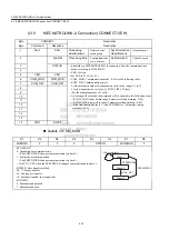
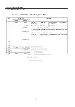
4.3.5
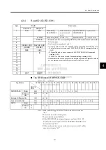
Set Up Device (CONFIG: 04H)
* +
α
refers to the amount of delay that is set by parameter for turning the Servo OFF during brak-
ing control.
Status and Output Signal during CONFIG Command Execution
Byte
CONFIG
Description
Command
Response
1
04H
04H
Processing
classifications
Control com-
mand group
Synchronization
classifications
Asynchronous
2
ALARM
Processing time
Within 4 s +
α
∗
Subcommand
Cannot be used.
3
STATUS
• Recalculates all currently set parameters and initializes positions, signals, etc.
• Can be used during phases 2 and 3.
• The SERVOPACK will change to Servo OFF if this command is received
when the SERVOPACK is Servo ON.
• A warning will occur and the command will be ignored in the following cases.
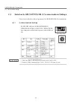
- During phase 1: MECHATROLINK-II command warning (A.95)
- If a digital operator is connected: MECHATROLINK-II command warning
(A.95)
- If SigmaWin and so on are connected: MECHATROLINK-II command
warning (A.95)
• The following table shows status and output signal during CONFIG command
execution.
• If communications are in progress with a Digital Operator, a command warn-
ing (A.ED) may occur.
4
5
6
7
8
9
10
11
12
13
14
15
16
WDT
RWDT
Status and
Output Signal
Before CONFIG
During CONFIG
After CONFIG
ALM (status)
Current status
Current status
Current status
CMDRDY (status)
1
0
1
Other status
Current status
Not specified
Current status
ALARM (code)
Alarms currently
occurred
Alarms currently
occurred
Alarms currently
occurred
ALM
(CN1 output signal)
Current status
Current status
Current status
/S-RDY
(CN1 output signal)
Current status
OFF
Current status
Other output signals
Current status
Not specified
Current status


