


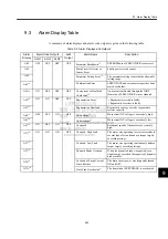

9.3 Alarm Display Table
9-25
9
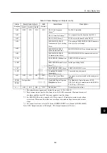
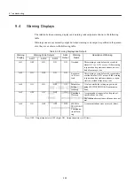
* 1. This alarm display appears only within the range of 30 W to 1000 W.
* 2. These alarms are not reset for the alarm clear (ALM-CLR) command. Eliminate the cause of
the alarm and then turn OFF the power supply to reset the alarms.
* 3. For SERVOPACKs with a capacity of 6.0 kw or more, A.40 indicates a main circuit voltage
error alarm. This means that either an overvoltage or an undervoltage has occurred at some
stage.
* 4. For corrective actions, refer to
Σ
-II Series SGM
H/SGDH User’s Manual (SIEPS80000005)
.
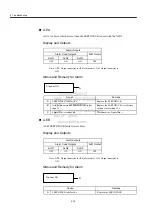
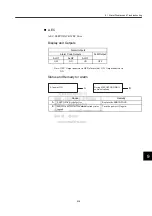
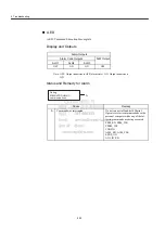
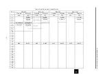
Note: OFF: Output transistor is OFF (high). ON: Output transistor is ON (low).
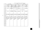
A.E0
OFF
ON
ON
OFF
NS115 No Response
Alarm
∗
2
No NS115 installed.
A.E1
NS115 Time Out Alarm
∗
2
No response from the board in the NS115.
A.E2
NS115 WDC Error
∗
2
WDC error in the board in the NS115
A.E4
MECHATROLINK-II
Transmission Cycle Setting
Error
The setting of MECHATROLINK-II transmis-
sion cycle is out of range.
A.E5
MECHATROLINK-II
Synchronization Error
MECHATROLINK-II synchronization error
A.E6
MECHATROLINK-II
Communications Error
MECHATROLINK-II communications error
A.EA
SERVOPACK Malfunction
∗
2
SERVOPACK is defective.
A.EB
SERVOPACK Initial Access
Error
∗
2
Initial processing failed.
A.EC
SERVOPACK WDC Error
SERVOPACK WDC error
A.ED
Command Execution
Incomplete
Command was interrupted.
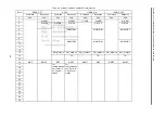
A.F1
OFF
ON
OFF
OFF
Power Line Open Phase
One phase is not connected in the main power
supply.
CPF00
Not specified
Hand-held Digital Operator
Transmission Error
The Hand-held Digital Operator (JUSP-
OP02A-2) fails to communicate with SERVO-
PACK (e.g., CPU error).
CPF01
A.
− −
OFF
OFF
OFF
ON
Not an error
Normal operation status
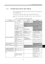
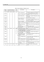
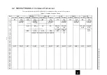
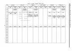
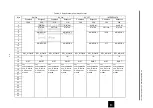
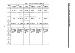
Table 9.2 Alarm Displays and Outputs (cont’d)
Alarm
Display
Alarm Code Outputs
ALM
Output
Alarm Name
Description
ALO1
ALO2
ALO3


