


6.3 Settings According to Host Controller
6-21
6
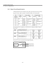
Electronic Gear Setting Examples
The following examples show electronic gear settings for different load mechanisms.
Ball Screws
Circular Tables
Belts and Pulleys
Preset
Values
Pn202
8192
Pn203
6000
Preset
Values
Pn202
24576
Pn203
3600
Preset
Values
Pn202
49152
Pn203
61810
Ball screw pitch: 6mm (0.24 in)
13-bit incremental
encoder
Load shaft
Reference unit: 0.001 mm (0.00004 in)
Tr avel d istance per load shaft revolution =
6 mm
0.001 mm
= 6000
E lect ro n ic gear ratio
B
A
=
2048
×
4
×
1
6000
×
1
=
Pn 202
Pn 203
13-bit incremental encoder
Load shaft
Travel distance per load shaft revolut ion = 360
°
0.1
°
= 3600
Electo nic gear ratio B
A
= 2048
×
4
×
3
3600
×
1
= Pn202
Pn203
Reference unit: 0.1
°
Deceleration
ratio: 3:1
Load shaft
Travel distance per load shaft revolution =
3.14
×
100 mm
0.0254 mm
= 12362
El ectron ic gear ratio
B
A
=
1024
×
4
×
2.4
1236 2
×
1
=
Pn 202
Pn 203
Deceleration
ratio: 2.4:1
Reference unit: 0.0254 mm (0.0010 in)
Pulley diameter:
φ
100 mm
Set a PG dividing ratio equivalent
to 1024 P/R for the absolute
encoder.
=
9830 .4
1236 2
=
49152
61810


