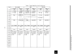
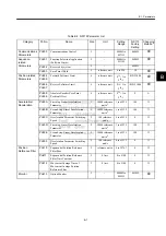
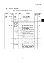


B.2 Function Switches
B-11
B
Function
Switches
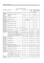
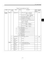
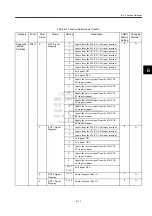
Pn003 0
Analog Monitor
1
0
Motor speed Rotary: 1 V/1000 min
-1
.
Linear: 1 V/1000 mm/s.
2
1
Speed reference Rotary: 1 V/1000 min
-1
.
Linear: 1 V/1000 mm/s.
2
Torque/thrust reference: 1 V/100%
3
Position error: 0.05 V/1 pulse
4
Position error: 0.05 V/100 pulses
5
Reference pulse frequency (converted to min
-1
)
Rotary: 1 V/1000 min
-1
.
Linear: 1 V/1000 mm/s.
6
Motor speed: Rotary: 1 V/250 min
-1
.
Linear: 1 V/100 mm/s.
7
Motor speed: Rotary: 1 V/125 min
-1
.
Linear: 1 V/10 mm/s.
8
Do not set.
9
Do not set.
A
Do not set.
B
Do not set.
C
Do not set.
D
Do not set.
E
Do not set.
F
Do not set.
1
Analog Monitor
2
0 to F
Same settings as Pn003.0.
0
2
Reserved by
system
Set to 0.
0
3
Reserved by
system
Set to 0.
0
Pn005 0
Brake Control
Function
Selection
0
Controls brakes with Servo.
0
∆
1
Controls brakes with controller.
1
Reserved by
system
Set to 0.
0
2
Reserved by
system
Set to 0.
0
3
Reserved by
system
Set to 0.
0
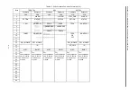
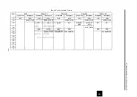
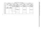
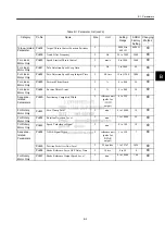
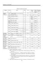
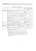
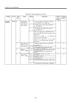
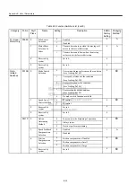
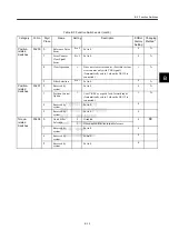
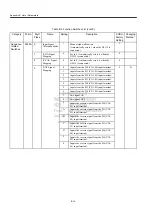
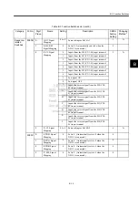
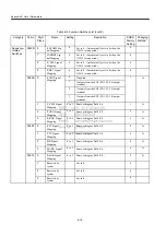
Table B.3 Function Switches List (cont’d)
Category
Pn No.
Digit
Place
Name
Setting
Description
SGDH
Factory
Setting
Changing
Method *


