Description
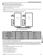
Jockey Pump
Run Priority
P9-21 = 7
P9-21 = 8
P9-21 = 8
Lead Swap @ Sleep
P9-24 = 0
P9-24 = 1200 s
P9-24 = 1200 s
Setpoint
U5-99 = 100 PSI
U5-99 = 100 PSI
U5-99 = 100 PSI
Start Level
P1-04 = 80 PSI
P1-04 = 80 PSI
P1-04 = 80 PSI
<1> All other multiplexing and alternation parameters are set to default settings.
Triplex System Example
A customer who currently runs a duplex system would like to retrofit an existing triplex system with the following requirements:
• Three similarly sized pumps would run the system.
• A maximum of two drives should be running at any point; the third drive is a backup.
• Alternation should only happen when pumps are not running (sleeping).
• If one of the analog pressure feedback transducers should fail, read from a working one and notify the customer of the failure
by the alarm display.
• Setpoint is 90 PSI, feedback scale is 145 PSI, start level is 75 PSI.
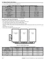
Drive A
25 HP
R+
S+
S-
R-
A2
AC
+V
A1
SN
S1
Drive B
25 HP
R+
S+
S-
R-
A2
AC
+V
A1
SN
S1
SYSTEM PRESSURE
FEEDBACK
Drive C
25 HP
R+
S+
S-
R-
A2
AC
+V
A1
SN
S1
SYSTEM PRESSURE
FEEDBACK
SYSTEM PRESSURE
FEEDBACK
Figure 4.23 Simplified Wiring Diagram
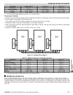
Table 4.13 Related Parameters for Triplex System Example
Description
Drive A
Node Address
H5-01 = 1
H5-01 = 2
H5-01 = 3
Highest Node Address
P9-25 = 3
P9-25 = 3
P9-25 = 3
Pump Mode: 3 (Network)
P1-01 = 3
P1-01 = 3
P1-01 = 3
Feedback Source: 2 (Analog ->Net,
with Alarm)
P9-02 = 2
P9-02 = 2
P9-02 = 2
Alternation Mode: 3 (FIFO @ Sleep)
P9-04 = 3
P9-04 = 3
P9-04 = 3
Maximum Running Pumps
P9-23 = 2
P9-23 = 2
P9-23 = 2
Setpoint
U5-99 = 90 PSI
U5-99 = 90 PSI
U5-99 = 90 PSI
Start Level
P1-04 = 75 PSI
P1-04 = 75 PSI
P1-04 = 75 PSI
<1> All other multiplexing and alternation parameters are set to default settings.
n
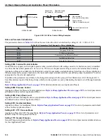
Multiplexing Stop History
Many irrigation-pumping skids consist of a PM pump (Pressure Maintenance) and typically two larger booster pumps to
maintain high flow peak demands. In many cases depending on the number of irrigation zones in combination with the type
of sprinkler heads used, the flow demand fluctuates and may not require the use of both larger booster pumps at the same time
until higher flow rates are required. The drive Controller "Run Stop" history ensures that both booster pumps alternate each
run cycle.
4.5 iQpump Presets and Functions
YASKAWA
TOEP YAIP1W 01A YASKAWA AC Drive - iQpump1000 Quick Start Guide
147
4
Start-Up Programming & Operation
Summary of Contents for iQpump1000
Page 355: ......


