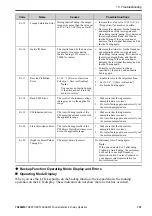
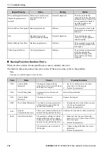
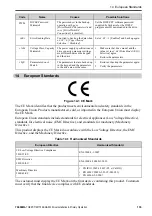
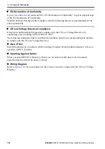
background image

14 European Standards

136

YASKAWA

TOEPC71061752B GA500 Drive Installation & Primary Operation

*5

Set

L8-05 = 1 [Output Phase Loss Protect Select = Enabled]

or set the wiring sequence to prevent input phase loss.

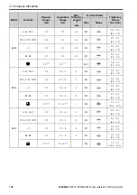
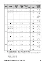
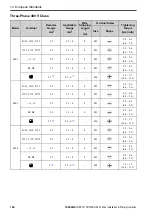
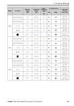
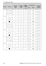
Main Circuit Wire Gauges and Tightening Torques

WARNING

Electrical Shock Hazard. Make sure that the protective ground wire complies with

technical standards and local safety regulations. The EN 61800-5-1: 2007 standard specifies that users must wire
the power supply to automatically turn off when the protective ground wire disconnects. If you turn on the internal
EMC filter, the leakage current of the drive will be more than 3.5 mA. You can also connect a protective ground
wire that has a minimum cross-sectional area of 10 mm

2

(copper wire). If you do not obey the standards and

regulations, it can cause serious injury or death.

WARNING

Electrical Shock Hazard. Only connect factory-recommended devices or circuits to drive

terminals B1, B2, -, +1, and +2. Do not connect AC power to these terminals. Incorrect wiring can cause damage
to the drive and serious injury or death from fire.

Note:

The recommended wire gauges are based on drive continuous current ratings with 75 °C (167 °F) 600 V class 2 heat-
resistant indoor PVC wire. Assume these conditions:

Ambient temperature: 40 °C (104 °F) maximum

Wiring distance: 100 m (3281 ft) maximum

Normal Duty rated current value

Refer to the instruction manual for each device for recommended wire gauges to connect peripheral devices or options
to ter1, +2, -, B1, and B2. Contact Yaskawa or your nearest sales representative if the recommended wire
gauges for the peripheral devices or options are out of the range of the applicable gauges for the drive.

Wire Selection Precautions

WARNING

Electrical Shock Hazard.

Make sure that the protective ground wire complies with technical standards and local safety regulations. The EN
61800-5-1:2007 standard specifies that you must wire the power supply to automatically de-energize when the
protective ground wire disconnects. If you turn on the internal EMC filter, the leakage current of the drive will be
more than 3.5 mA. Use these closed-loop crimp terminals or equivalent to connect a protective ground wire that
has a minimum cross-sectional area of 10 mm

2

(copper wire).

• 8-4NS from JST Mfg. Co., Ltd.
• R8-4S from NICHIFU Co., Ltd.
• P10-8R from PANDUIT Corp.

If you do not obey the standards and regulations, it can cause serious injury or death.

Think about line voltage drop before selecting wire gauges. Select wire gauges that drop the
voltage by 2% or less of the rated voltage. Increase the wire gauge and the cable length when the
risk of voltage drops increases. Calculate line voltage drop with this formula:

Line voltage drop (V) =

× wire resistance (Ω/km) × wiring distance (m) × motor rated

current (A) × 10

-3

.

Precautions during Wiring

Refer to

Yaskawa AC Drive Option Braking Unit, Braking Resistor Unit Instruction Manual

(TOBPC72060001)

for information about wire gauges and tightening torques to connect

braking resistor units.

Use ter1 and - to connect a regenerative converter or regenerative unit.

WARNING

Fire Hazard. Do not connect a braking resistor to ter1 or -. Use terminals B1 and

B2 for the braking resistor connections. If you connect a braking resistor to the incorrect terminals, it can cause
damage to the drive and braking circuit and serious injury or death.

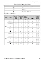
Screw Shape

These tables use icons in

Table 14.2

to show the shapes of the screw heads.

Summary of Contents for GA50U Series

Page 1: ...A500 Industrial AC Microdrive Installation Primary Operation Catalog Code GA50Uxxxxxxxx 240 V Single Phase Input 1 6 to 5 HP 240 V Three Phase Input 1 6 to 30 HP 480 V Three Phase Input 1 2 to 40 HP PDF ...

Page 2: ...This Page Intentionally Blank 2 YASKAWA TOEPC71061752B GA500 Drive Installation Primary Operation ...

Page 3: ...nd Functions 18 Keypad Mode and Menu Displays 21 7 Mechanical Installation 22 Drive Exterior and Mounting Dimensions 22 IP20 UL Open Type 22 Installation Position and Clearances 28 Removing Reattaching Covers 30 Remove the Front Cover 30 Reattach the Front Cover 31 8 Electrical Installation 32 Standard Connection Diagram 33 Main Circuit Terminal Block Wiring Procedure 35 Wire to the Main Circuit T...

Page 4: ...ctor Control Method 72 ASR and Inertia Tuning 73 Precautions before Auto Tuning 74 Prepare for Basic Auto Tuning 74 Precautions before Rotational Auto Tuning 75 Precautions before Stationary Auto Tuning 76 Automatically Set E2 02 Motor Rated Slip and E2 03 Motor No Load Current 76 Precautions before Stationary Auto Tuning for Line to Line Resistance and Stator Resistance Auto Tuning 76 Precautions...

Page 5: ...62 Factory Recommended Branch Circuit Protection 175 Low Voltage Wiring for Control Circuit Terminals 178 Drive Motor Overload and Overheat Protection 178 E2 01 Motor Rated Current FLA 179 E5 03 Motor Rated Current FLA 179 E9 06 Motor Rated Current FLA 179 L1 01 Motor Overload oL1 Protection 180 L1 02 Motor Overload Protection Time 183 L1 03 Motor Thermistor oH Alarm Select 184 L1 04 Motor Thermis...

Page 6: ...6 YASKAWA TOEPC71061752B GA500 Drive Installation Primary Operation Revision History 196 ...

Page 7: ...of the equipment or the customer who assembles the final product Yaskawa is not responsible for how our products are incorporated into the final system design In all cases Yaskawa products should not be incorporated into a product or design as the exclusive or sole safety control function All control functions are designed to dynamically detect failures and operate safely without exception All pro...

Page 8: ...stall wire maintain examine replace parts and repair the drive If personnel are not approved it can cause serious injury or death WARNING Electrical Shock Hazard Do not remove covers or touch circuit boards while the drive is energized If you touch the internal components of an energized drive it can cause serious injury or death WARNING Electrical Shock Hazard After the drive blows a fuse or trip...

Page 9: ...dicine airplanes and aerospace nuclear power electric power or undersea relaying WARNING Injury to Personnel When you use this product in applications where its failure could cause the loss of human life a serious accident or physical injury you must install applicable safety devices If you do not correctly install safety devices it can cause serious injury or death 3 Drive Specifications Note To ...

Page 10: ...sign IP20 UL Open Type IP20 UL Type 1 Note Install a UL Type 1 kit optional on an IP20 UL Open Type drive to change the drive to an IP20 UL Type 1 enclosure Table 3 3 Protection Functions Item Specification Motor Protection Electronic thermal overload protection Momentary Overcurrent Protection Drive stops when the output current is more than 200 of the HD output current Overload Protection Drive ...

Page 11: ...e drive will not provide protection when There is a low resistance ground fault for the motor cable or terminal block Energizing the drive when there is a ground fault DC Bus Charge LED Charge LED illuminates when DC bus voltage is more than 50 V Table 3 4 Control Characteristics Item Specification Control Methods V f Control Open Loop Vector PM Open Loop Vector PM Advanced Open Loop Vector EZ Vec...

Page 12: ...rameter incorrectly the drive can decelerate for too long and cause serious injury or death Note Short time average deceleration torque refers to the torque needed to decelerate the motor uncoupled from the load from the rated speed to zero Motor characteristics can change the actual specifications Motor characteristics change the continuous regenerative torque and short time average deceleration ...

Page 13: ...e or missing parts Immediately contact the shipping company if the drive is damaged The Yaskawa warranty does not cover damage from shipping 2 Examine the catalog code to make sure that you received the correct model Examine the catalog code in the C C section of the drive nameplate to make sure that you received the correct model 3 Contact your supplier or Yaskawa sales office if you received an ...

Page 14: ...a Electric Corporation D Accreditation standards E Ambient temperature specification F Enclosure protection design G Product number H Serial number I Output specifications J Input specifications K Catalog code Figure 5 1 Nameplate Information Example How to Read the Catalog Code Use the information in Figure 5 2 and Table 5 1 to read the drive catalog code ...

Page 15: ... 5 3 and Table 5 4 for the rated output current by model 5 EMC noise filter A No internal EMC filter E Built in EMC Filter 6 Enclosure protection design B IP20 UL Open Type 7 Environmental specification A Standard Rated Output Current Table 5 2 Table 5 3 and Table 5 4 give the rated output current values Note Rated output current values are applicable for drives that operate at standard specificat...

Page 16: ... 2 8 0 2 2 3 9 6 B012 2 2 3 11 0 3 0 3 12 2 B018 3 7 5 17 6 Table 5 3 Three Phase AC 200 V Class Model Heavy Duty Rating HD C6 01 0 Normal Duty Rating ND C6 01 1 Default Maximum Applicable Motor Output kW HP Rated Output Current A Maximum Applicable Motor Output kW HP Rated Output Current A 2001 0 1 1 6 0 8 0 2 1 6 1 2 2002 0 2 1 4 1 6 0 4 1 4 1 9 2004 0 4 1 2 3 0 0 75 3 4 3 5 2006 0 75 1 5 0 1 1 ...

Page 17: ...t Current A Maximum Applicable Motor Output kW HP Rated Output Current A 4001 0 2 1 2 1 2 0 4 1 2 1 2 4002 0 4 3 4 1 8 0 75 1 2 1 4004 0 75 2 3 4 1 5 2 4 1 4005 1 5 3 4 8 2 2 3 5 4 4007 2 2 3 5 6 3 0 4 7 1 4009 3 0 4 7 3 3 7 5 8 9 4012 3 7 5 9 2 5 5 7 5 11 9 4018 5 5 10 14 8 7 5 10 17 5 4023 7 5 10 18 0 11 0 15 23 4 4031 11 0 15 24 0 15 0 20 31 0 4038 15 0 20 31 0 18 5 25 38 0 4044 18 5 25 39 0 22...

Page 18: ...ypad to operate the motor push on the keypad to set the drive to LOCAL Mode C STOP Key Stops drive operation Note Uses a stop priority circuit Push to stop the motor This will also apply when a Run command REMOTE Mode is active at an external Run command source To disable priority set o2 02 0 STOP Key Function Selection Disabled D LO RE LED Illuminated The keypad controls the Run command LOCAL Mod...

Page 19: ...drive is stopped Flashing The drive is decelerating to stop The drive received a Run command but the frequency reference is 0 Hz Flashing quickly When the drive is in LOCAL Mode the drive received a Run command from the MFDI terminals and is switched to REMOTE Mode The drive received a Run command from the MFDI terminals when the drive is not in Drive Mode The drive received a Fast Stop command Th...

Page 20: ...0 LO RE Key Function Selection Disabled to disable The drive will not switch between LOCAL and REMOTE when it is receiving a Run command from an external source L REV LED Illuminated The drive received a Reverse run command M DWEZ LED Illuminated The drive is In DriveWorksEZ operation N RJ 45 Connector Connects to the drive Use an RJ 45 8 pin straight through UTP CAT5e extension cable to install t...

Page 21: ...6 Overview of Keypad Components and Functions YASKAWA TOEPC71061752B GA500 Drive Installation Primary Operation 21 Keypad Mode and Menu Displays Figure 6 2 Keypad Functions and Display Levels ...

Page 22: ... to B004 2001 to 2006 Figure 7 1 Exterior and Mounting Dimensions Table 7 1 Single Phase 200 V Class IP20 UL Open Type without Built in EMC Filter Model Dimensions mm in Est Weight kg lb W H D W1 W2 H1 H2 D1 t1 d B001A 68 2 68 128 5 04 76 2 99 56 2 20 6 0 24 118 4 65 5 0 20 6 5 0 26 3 0 12 M5 0 5 1 1 B002A 68 2 68 128 5 04 76 2 99 56 2 20 6 0 24 118 4 65 5 0 20 6 5 0 26 3 0 12 M5 0 5 1 1 B004A 68 ...

Page 23: ...1A 68 2 68 128 5 04 76 2 99 56 2 20 6 0 24 118 4 65 5 0 20 6 5 0 26 3 0 12 M5 0 5 1 1 2002A 68 2 68 128 5 04 76 2 99 56 2 20 6 0 24 118 4 65 5 0 20 6 5 0 26 3 0 12 M5 0 5 1 1 2004A 68 2 68 128 5 04 108 4 25 56 2 20 6 0 24 118 4 65 5 0 20 38 5 1 52 5 0 20 M5 0 8 1 8 2006A 68 2 68 128 5 04 128 5 04 56 2 20 6 0 24 118 4 65 5 0 20 58 5 2 30 5 0 20 M5 0 9 2 0 Table 7 4 Three Phase 200 V Class IP20 UL O...

Page 24: ... 78 6 0 24 118 4 65 5 0 20 56 5 2 22 5 0 20 M5 1 5 3 3 B012A 140 5 51 128 5 04 163 6 42 128 5 04 6 0 24 118 4 65 5 0 20 65 2 56 5 0 20 M5 2 1 4 6 B018A 170 6 69 128 5 04 180 7 09 158 6 22 6 0 24 118 4 65 5 0 20 65 2 56 5 0 20 M5 2 9 6 4 Table 7 6 Single Phase 200 V Class IP20 UL Open Type with Built in EMC Filter Model Dimensions mm in Est Weight kg lb W H D W1 W2 H1 H2 D1 t1 d B006E 108 4 25 128 ...

Page 25: ... 4 25 128 5 04 182 5 7 19 96 3 78 6 0 24 118 4 65 5 0 20 56 5 2 22 5 0 20 M5 1 6 3 5 2021E 140 5 51 128 5 04 193 7 60 128 5 04 6 0 24 118 4 65 5 0 20 65 2 56 5 0 20 M5 2 4 5 3 Table 7 9 Three Phase 400 V Class IP20 UL Open Type without Built in EMC Filter Model Dimensions mm in Est Weight kg lb W H D W1 W2 H1 H2 D1 t1 d 4001A 108 4 25 128 5 04 81 3 19 96 3 78 6 0 24 118 4 65 5 0 20 8 5 0 33 5 0 20...

Page 26: ...24 118 4 65 5 0 20 26 5 1 04 5 0 20 M5 1 5 3 3 4004E 108 4 25 128 5 04 182 5 7 19 96 3 78 6 0 24 118 4 65 5 0 20 56 5 2 22 5 0 20 M5 1 9 4 2 4005E 108 4 25 128 5 04 199 7 83 96 3 78 6 0 24 118 4 65 5 0 20 56 5 2 22 5 0 20 M5 1 9 4 2 4007E 108 4 25 128 5 04 199 7 83 96 3 78 6 0 24 118 4 65 5 0 20 56 5 2 22 5 0 20 M5 1 9 4 2 4009E 108 4 25 128 5 04 199 7 83 96 3 78 6 0 24 118 4 65 5 0 20 56 5 2 22 5...

Page 27: ...t kg lb W H D W1 W2 H1 H2 D1 t1 d 2030E 140 5 51 260 10 24 196 7 72 122 4 80 9 0 35 248 9 76 6 0 24 55 2 17 5 0 20 M5 3 9 8 6 2042E 140 5 51 260 10 24 196 7 72 122 4 80 9 0 35 248 9 76 6 0 24 55 2 17 5 0 20 M5 4 1 9 0 2056E 180 7 09 300 11 81 196 7 72 160 6 30 10 0 39 284 11 18 8 0 31 55 2 17 5 0 20 M5 6 0 13 2 2070E 220 8 66 350 13 78 216 8 50 192 7 56 14 0 55 336 13 23 7 0 28 78 3 07 5 0 20 M6 8...

Page 28: ...5 51 260 10 24 196 7 72 122 4 80 9 0 35 248 9 76 6 0 24 55 2 17 5 0 20 M5 3 9 8 6 4031E 180 7 09 300 11 81 196 7 72 160 6 30 10 0 39 284 11 18 8 0 31 55 2 17 5 0 20 M5 5 5 12 1 4038E 180 7 09 300 11 81 196 7 72 160 6 30 10 0 39 284 11 18 8 0 31 55 2 17 5 0 20 M5 5 5 12 1 4044E 190 7 48 350 13 78 251 9 88 160 6 30 15 0 59 336 13 23 7 0 28 94 3 70 5 0 20 M6 8 0 17 6 4060E 190 7 48 350 13 78 251 9 88...

Page 29: ...for wiring and airflow A 50 mm 2 in minimum between upper and lower openings B 30 mm 1 18 in minimum on each side C 100 mm 3 94 in minimum above and below D Airflow direction Figure 7 5 Installation Clearances for One Drive Install Drives Side by Side When you install drives side by side set to L8 35 1 Installation Method Selection Side by Side Mounting Refer to the Technical Reference and derate ...

Page 30: ... on an energized drive Before servicing disconnect all power to the equipment and wait for the time specified on the warning label at a minimum The internal capacitor stays charged after the drive is de energized The charge indicator LED extinguishes when the DC bus voltage decreases below 50 Vdc When all indicators are OFF measure for dangerous voltages to make sure that the drive is safe If you ...

Page 31: ...Figure 7 7 Unlocking 2 Pull down then pull away from the drive to remove the front cover Figure 7 8 Remove the Front Cover Reattach the Front Cover 1 Reverse the steps to reattach the cover Note Make sure that you do not pinch wires or signal lines between the front cover and the drive before you reattach the cover ...

Page 32: ... energized The charge indicator LED extinguishes when the DC bus voltage decreases below 50 Vdc When all indicators are OFF measure for dangerous voltages to make sure that the drive is safe If you do work on the drive when it is energized it will cause serious injury or death from electrical shock WARNING Electrical Shock Hazard De energize the drive and wait 5 minutes minimum until the Charge LE...

Page 33: ...sting RUN Command default If you do not correctly set the drive parameters for 3 Wire operation before you energize the drive the motor can suddenly rotate when you energize the drive WARNING Sudden Movement Hazard Check the I O signals and the external sequences for the drive before you set the Application Preset function When you set the Application Preset function A1 06 0 it changes the I O ter...

Page 34: ...et the wiring sequence to de energize the drive with the MFDO If the drive outputs a fault during fault restart when you use the fault restart function set L5 02 1 Fault Contact at Restart Select Always Active to de energize the drive Be careful when you use a cut off sequence The default setting for L5 02 is 0 Active Only when Not Restarting ...

Page 35: ...its terminals SC SP and terminals SC SN it will cause damage to the drive External power supply Remove the jumper from the MFDI terminals It is not necessary to close the circuit between terminals SC SP and terminals SC SN 10 The maximum output current capacity for terminal Von the control circuit is 20 mA NOTICE Damage to Equipment Do not install a jumper between terminals V and AC A closed circu...

Page 36: ...e wire all the way into the terminal block Remove the insulation from the wire to the recommended wire stripping length to fit the wire with insulation in the plastic housing Use a torque driver torque ratchet or torque wrench for the screws A slotted driver or a hex tool will be necessary to wire the screw clamp terminal Use applicable tools as specified by the recommended conditions in the produ...

Page 37: ...e A Cable clamp Figure 8 4 Strain Relief Example Table 8 1 Recommended Wiring Tools Screw Size Screw Shape Wire Gauge Adapter Bit Torque Driver Model Tightening Torque Torque Wrench Tightening Torque Model Manufacturer M3 Bit SF BIT SL 0 5X3 0 70 PHOENIX CONTACT TSD M 1 2NM 0 3 1 2 N m 2 7 10 6 in lb M4 Bit SF BIT SL 1 0X4 0 70 PHOENIX CONTACT TSD M 3NM 1 2 3 0 N m 10 6 26 6 in lb M5 1 25 mm2 AWG ...

Page 38: ...ave IP20 terminal protective covers remove the cover on the terminal where you will wire 1 Put wires with prepared ends into the main circuit terminal block Look through the opening in the drive case to make sure that you correctly installed the wires into the terminal block Figure 8 5 Install the Electrical Wire Note There is a jumper between terminals 1 and 2 Remove the jumper then wire to termi...

Page 39: ... connection 2 B1 Braking resistor connection To connect a braking resistor or braking resistor unit B2 Ground Wiring To ground the drive 200 V D class grounding ground to 100 Ω or less 400 V C class grounding ground to 10 Ω or less Wire Selection Select the correct wires for main circuit wiring Refer to Main Circuit Wire Gauges and Tightening Torques on page 136 for wire gauges and tightening torq...

Page 40: ... U T1 V T2 W T3 14 14 6 5 M3 0 5 0 6 4 4 5 3 1 14 14 6 5 M3 0 5 0 6 4 4 5 3 B1 B2 14 14 6 5 M3 0 5 0 6 4 4 5 3 14 2 14 2 M3 5 0 8 1 0 7 1 8 9 B002 L L1 N L2 14 14 6 5 M3 0 5 0 6 4 4 5 3 U T1 V T2 W T3 14 14 6 5 M3 0 5 0 6 4 4 5 3 1 14 14 6 5 M3 0 5 0 6 4 4 5 3 B1 B2 14 14 6 5 M3 0 5 0 6 4 4 5 3 14 2 14 2 M3 5 0 8 1 0 7 1 8 9 B004 L L1 N L2 14 14 6 5 M3 0 5 0 6 4 4 5 3 U T1 V T2 W T3 14 14 6 5 M3 0...

Page 41: ...12 8 M3 0 5 0 6 4 4 5 3 1 12 14 10 8 M3 0 5 0 6 4 4 5 3 B1 B2 14 14 12 8 M3 0 5 0 6 4 4 5 3 10 2 14 10 2 M4 1 2 1 5 10 6 13 3 B010 L L1 N L2 10 12 10 8 M3 0 5 0 6 4 4 5 3 U T1 V T2 W T3 14 14 12 8 M3 0 5 0 6 4 4 5 3 1 10 12 10 8 M3 0 5 0 6 4 4 5 3 B1 B2 14 14 12 8 M3 0 5 0 6 4 4 5 3 10 2 14 10 2 M4 1 2 1 5 10 6 13 3 B012 L L1 N L2 8 14 8 10 M4 1 5 1 7 13 5 15 U T1 V T2 W T3 12 14 10 10 M4 1 5 1 7 ...

Page 42: ...5 1 7 13 5 15 1 8 12 6 10 M4 1 5 1 7 13 5 15 B1 B2 14 14 12 10 M4 1 5 1 7 13 5 15 8 2 12 8 2 M5 2 0 2 5 17 7 22 1 1 Remove insulation from the ends of wires to expose the length of wire shown 2 If you turn on the internal EMC filter the leakage current of the drive will be more than 3 5 mA Use these closed loop crimp terminals or equivalent to connect a protective ground wire that has a minimum cr...

Page 43: ...V T2 W T3 14 14 6 5 M3 0 5 0 6 4 4 5 3 1 2 14 14 6 5 M3 0 5 0 6 4 4 5 3 B1 B2 14 14 6 5 M3 0 5 0 6 4 4 5 3 14 2 14 2 M3 5 0 8 1 0 7 1 8 9 2002 R L1 S L2 T L3 14 14 6 5 M3 0 5 0 6 4 4 5 3 U T1 V T2 W T3 14 14 6 5 M3 0 5 0 6 4 4 5 3 1 2 14 14 6 5 M3 0 5 0 6 4 4 5 3 B1 B2 14 14 6 5 M3 0 5 0 6 4 4 5 3 14 2 14 2 M3 5 0 8 1 0 7 1 8 9 2004 R L1 S L2 T L3 14 14 6 5 M3 0 5 0 6 4 4 5 3 U T1 V T2 W T3 14 14 ...

Page 44: ... M3 0 5 0 6 4 4 5 3 1 2 14 14 6 5 M3 0 5 0 6 4 4 5 3 B1 B2 14 14 6 5 M3 0 5 0 6 4 4 5 3 14 2 14 2 M3 5 0 8 1 0 7 1 8 9 2010 R L1 S L2 T L3 14 14 12 8 M3 0 5 0 6 4 4 5 3 U T1 V T2 W T3 14 14 12 8 M3 0 5 0 6 4 4 5 3 1 2 12 14 10 8 M3 0 5 0 6 4 4 5 3 B1 B2 14 14 12 8 M3 0 5 0 6 4 4 5 3 10 2 14 10 2 M4 1 2 1 5 10 6 13 3 2012 R L1 S L2 T L3 12 14 10 8 M3 0 5 0 6 4 4 5 3 U T1 V T2 W T3 12 14 10 8 M3 0 5...

Page 45: ...1 5 1 7 13 5 15 1 2 8 14 8 10 M4 1 5 1 7 13 5 15 B1 B2 14 14 10 10 M4 1 5 1 7 13 5 15 8 14 8 M4 1 2 1 5 10 6 13 3 2030 R L1 S L2 T L3 8 12 6 10 M4 1 5 1 7 13 5 15 U T1 V T2 W T3 8 12 6 10 M4 1 5 1 7 13 5 15 1 2 6 12 6 10 M4 1 5 1 7 13 5 15 B1 B2 12 12 8 10 M4 1 5 1 7 13 5 15 8 10 6 M5 2 0 2 5 17 7 22 1 2042 R L1 S L2 T L3 6 12 6 10 M4 1 5 1 7 13 5 15 U T1 V T2 W T3 6 12 6 10 M4 1 5 1 7 13 5 15 1 2...

Page 46: ...2 W T3 2 8 1 20 M6 5 5 5 45 49 1 2 1 6 1 0 20 M6 5 5 5 45 49 B1 B2 8 12 6 10 M4 1 5 1 7 13 5 15 4 6 4 M6 5 4 6 0 47 8 53 1 2082 R L1 S L2 T L3 1 6 1 0 20 M6 5 5 5 45 49 U T1 V T2 W T3 2 6 1 20 M6 5 5 5 45 49 1 2 2 0 2 2 0 20 M6 5 5 5 45 49 B1 B2 6 10 6 10 M4 1 5 1 7 13 5 15 4 6 4 M6 5 4 6 0 47 8 53 1 1 Remove insulation from the ends of wires to expose the length of wire shown 2 If you turn on the...

Page 47: ...14 14 12 8 M3 0 5 0 6 4 4 5 3 1 2 14 14 12 8 M3 0 5 0 6 4 4 5 3 B1 B2 14 14 12 8 M3 0 5 0 6 4 4 5 3 14 2 14 10 2 M4 1 2 1 5 10 6 13 3 4002 R L1 S L2 T L3 14 14 12 8 M3 0 5 0 6 4 4 5 3 U T1 V T2 W T3 14 14 12 8 M3 0 5 0 6 4 4 5 3 1 2 14 14 12 8 M3 0 5 0 6 4 4 5 3 B1 B2 14 14 12 8 M3 0 5 0 6 4 4 5 3 14 2 14 10 2 M4 1 2 1 5 10 6 13 3 4004 R L1 S L2 T L3 14 14 12 8 M3 0 5 0 6 4 4 5 3 U T1 V T2 W T3 14...

Page 48: ...3 0 5 0 6 4 4 5 3 1 2 14 14 12 8 M3 0 5 0 6 4 4 5 3 B1 B2 14 14 12 8 M3 0 5 0 6 4 4 5 3 10 2 14 10 2 M4 1 2 1 5 10 6 13 3 4007 R L1 S L2 T L3 14 14 12 8 M3 0 5 0 6 4 4 5 3 U T1 V T2 W T3 14 14 12 8 M3 0 5 0 6 4 4 5 3 1 2 14 14 12 8 M3 0 5 0 6 4 4 5 3 B1 B2 14 14 12 8 M3 0 5 0 6 4 4 5 3 10 2 14 10 2 M4 1 2 1 5 10 6 13 3 4009 R L1 S L2 T L3 14 14 12 8 M3 0 5 0 6 4 4 5 3 U T1 V T2 W T3 14 14 12 8 M3 ...

Page 49: ... M4 1 5 1 7 13 5 15 1 2 10 12 8 10 M4 1 5 1 7 13 5 15 B1 B2 14 14 12 10 M4 1 5 1 7 13 5 15 10 2 14 10 2 M4 1 2 1 5 10 6 13 3 4018 R L1 S L2 T L3 10 12 8 10 M4 1 5 1 7 13 5 15 U T1 V T2 W T3 10 12 8 10 M4 1 5 1 7 13 5 15 1 2 10 14 8 10 M4 1 5 1 7 13 5 15 B1 B2 14 14 12 10 M4 1 5 1 7 13 5 15 10 2 14 6 2 M5 2 0 2 5 17 7 22 1 4023 R L1 S L2 T L3 8 14 6 10 M4 1 5 1 7 13 5 15 U T1 V T2 W T3 10 14 8 10 M...

Page 50: ...hape 4031 R L1 S L2 T L3 8 12 6 10 M4 1 5 1 7 13 5 15 U T1 V T2 W T3 8 12 6 10 M4 1 5 1 7 13 5 15 1 2 6 12 4 18 M5 AWG 10 2 3 2 5 19 8 22 AWG 8 4 1 4 5 36 40 B1 B2 10 12 8 10 M4 1 5 1 7 13 5 15 8 10 6 M6 5 4 6 0 47 8 53 1 4038 R L1 S L2 T L3 6 12 6 10 M4 1 5 1 7 13 5 15 U T1 V T2 W T3 8 12 6 10 M4 1 5 1 7 13 5 15 1 2 4 10 2 18 M5 AWG 10 2 3 2 5 19 8 22 AWG 8 4 1 4 5 36 40 B1 B2 10 14 6 10 M4 1 5 1...

Page 51: ...4 1 4 5 36 40 1 2 2 6 2 18 M5 4 1 4 5 36 40 B1 B2 8 12 6 10 M4 1 5 1 7 13 5 15 6 10 6 M6 5 4 6 0 47 8 53 1 1 Remove insulation from the ends of wires to expose the length of wire shown 2 If you turn on the internal EMC filter the leakage current of the drive will be more than 3 5 mA Use these closed loop crimp terminals or equivalent to connect a protective ground wire that has a minimum cross sec...

Page 52: ...t F Input Protection Fuses or Circuit Breakers Note The locations of terminals are different for different drive models Figure 8 7 Wiring the Main Circuit and Motor Control Circuit Terminal Block Functions Hx xx parameters set functions for the multi function input and output terminals WARNING Sudden Movement Hazard Correctly wire and test all control circuits to make sure that the control circuit...

Page 53: ...he Application Preset function A1 06 0 it changes the I O terminal functions for the drive and it can cause equipment to operate unusually This can cause serious injury or death NOTICE Damage to Equipment Do not energize and de energize the drive more frequently than one time each 30 minutes If you frequently energize and de energize the drive it can cause drive failure Input Terminals Refer to Ta...

Page 54: ... will cause damage to the drive External power supply Remove the jumper from the MFDI terminals It is not necessary to close the circuit between terminals SC SP and terminals SC SN S2 MFDI selection 2 ON Reverse run OFF Stop S3 MFDI selection 3 External fault N O S4 MFDI selection 4 Fault reset S5 MFDI selection 5 Multi step speed reference 1 S6 MFDI selection 6 Multi step speed reference 2 S7 MFD...

Page 55: ...d to terminal A1 Voltage input or current input Use DIP switch S1 and H3 09 Terminal A2 Signal Level Select to select the input 0 V to 10 V 100 input impedance minimum 15 kΩ 10 V to 10 V 100 to 100 input impedance minimum 15 kΩ 4 mA to 20 mA 100 0 mA to 20 mA 100 input impedance 250 Ω AC Frequency reference common 0 V E G Connecting shielded cable Output Terminals Refer to Table 8 5 and Table 8 6 ...

Page 56: ...r Supply Input Terminals Type Terminal Name Default Function External Power Supply Input Terminals PS External 24 V power supply input Supplies backup power to the drive control circuit keypad and option board 21 6 VDC to 26 4 VDC 700 mA AC External 24 V power supply ground 0 V Serial Communication Terminals Refer to Table 8 8 for a list of serial communication terminals and functions Table 8 8 Se...

Page 57: ...nd Tightening Torques Terminal Block Terminal Screw Size Tightening Torque N m in lb Bare Wire Crimp Ferrule Recomm Gauge mm2 AWG Applicable Gauge mm2 AWG Recomm Gauge mm2 AWG Applicable Gauge mm2 AWG TB1 1 PS S1 S7 SN SC SP M2 0 22 0 25 1 95 2 21 0 75 18 Stranded wire 0 25 1 0 24 17 Solid wire 0 25 1 5 24 16 0 5 20 0 25 0 5 24 20 TB1 2 AM AC A1 A2 V H1 H2 HC TB1 3 MP RP AC D D P1 C1 P2 C2 TB2 MA ...

Page 58: ... power supply to connect external power to the control terminals If the power supply for peripheral devices is incorrect it can cause a decrease in drive performance Connect the shield of shielded cable to the applicable ground terminal Incorrect equipment grounding can cause drive or equipment malfunction from electrical interference Isolate wiring for contact output terminals MA MB MC P1 C1 P2 a...

Page 59: ...nections that are too loose or too tight can cause incorrect operation and damage to the drive Incorrect connections can also cause death or serious injury from fire Note Use shielded twisted pair wires and ground the shield to the ground terminal of the drive Incorrect equipment grounding can cause drive or equipment malfunction from electrical interference Do not use control circuit wiring that ...

Page 60: ...s Figure 8 11 Wiring Procedure for the Control Circuit Note It is easier to wire TB1 1 first then TB1 2 then TB1 3 Do not solder the core wire Soldered wiring connections can become loose and cause the drive to malfunction Tighten all terminal screws to the correct tightening torque Connections that are too loose or too tight can cause incorrect operation and damage to the drive Incorrect connecti...

Page 61: ... Jumper S5 attach the keypad before you attach the front cover If you did not move Jumper S5 attach the front cover Make sure that you do not pinch wires or signal lines between the front cover and the drive before you reattach the cover Figure 8 13 Reattach the Front Cover Switches and Jumpers on the Terminal Board The terminal board has switches to adapt the drive I Os to the external control si...

Page 62: ...esistor OFF Control I O Connections This section gives information about the settings for the listed control circuit I O signals MFDI terminals S1 to S7 Pulse train output terminal MP MFAI terminal A2 MFAO terminal AM MEMOBUS Modbus communications terminals D D AC Set Sinking Mode Sourcing Mode Close the circuit between terminals SC SP and SC SN to set the sinking mode sourcing mode and the intern...

Page 63: ...u can use pulse train monitor output terminal MP for sourcing mode or for sinking mode Use for sourcing mode The load impedance changes the voltage level of the pulse train output signal Load Impedance RL kΩ Output Voltage VMP V 1 5 kΩ or more 5 Vor more 4 0 kΩ or more 8 Vor more 10 kΩ or more 10 Vor more Note Use the formula in Figure 8 15 to calculate the necessary load resistance kΩ to increase...

Page 64: ...ge from an external source between 10 8 Vdc to 16 5 Vdc Adjust the load impedance to keep the current at 16 mA or lower External Power Supply V Load Impedance kΩ Sinking current mA 10 8 Vdc to 16 5 Vdc 1 0 kΩ or more 16 mA maximum A External power supply B Load Impedance C Sinking current Figure 8 16 Wiring to Use Pulse Train Output in Sinking Mode Set the Input Signal for the MFAI Terminal A2 Use...

Page 65: ... mA 0 to 100 input impedance 250 Ω 3 0 mA to 20 mA 0 to 100 input impedance 250 Ω Voltage input V 0 0 V to 10 V 0 to 100 with zero limit input impedance minimum 15 kΩ 4 10 V to 10 V 100 to 100 input impedance minimum 15 kΩ Note Use tweezers or a jig with a tip width of approximately 0 8 mm 0 03 in to set DIP switches Set the Output Signal for the MFAO Terminal AM Set the signal type for terminal A...

Page 66: ...arameter No Signal Level AM Voltage output Default H4 07 0 0 V to 10 V Current output 2 4 mA to 20 mA Switch ON Termination Resistor for MEMOBUS Modbus Communications When the drive is the last slave in a MEMOBUS Modbus communications set DIP switch S2 to the ON position This drive has a built in termination resistor for the RS 485 interface Figure 8 19 Location of DIP Switch S2 ...

Page 67: ...Crush Hazard Rotational Auto Tuning rotates the motor at 50 or more of the motor rated frequency Make sure that there are no issues related to safety in the area around the drive and motor Increased motor frequency can cause serious injury or death Auto Tuning for Induction Motors This section gives information about Auto Tuning for induction motors Set motor parameters E1 xx and E2 xx or for moto...

Page 68: ...proximately 1 minute During this time the drive automatically measures the necessary motor parameters When you operate the motor with less than 30 load after Auto Tuning Set T1 12 1 Test Mode Selection Yes to do a test run after Auto Tuning x Stationary Line Line Resistance T1 01 2 After Auto Tuning the wiring distance between the drive and motor changed by 50 m or more When the wiring distance is...

Page 69: ...e default value If you do not know the Motor Rated Slip Frequency keep the setting at 0 Hz 2 Input this value when A1 02 0 Control Method Selection V f 3 If T1 12 1 Test Mode Selection Yes when you run the motor in Drive Mode for the first time after Auto Tuning the drive will automatically set E2 02 Motor Rated Slip and E2 03 Motor No Load Current 4 Input this value when T1 10 Motor Rated Slip Fr...

Page 70: ...to Tuning the wiring distance between the drive and motor changed by 50 m 164 ft or more When the motor output and drive capacity are different x x PM Motor Code Selection T2 01 4 When the information from the motor test report or motor nameplate is not available When you can decouple the motor and load and the motor can rotate freely while Auto Tuning The drive will automatically set the values m...

Page 71: ...ection A1 02 5 6 5 6 5 6 5 6 PM Motor Code Selection T2 02 Motor code of Yaskawa motor 1 FFFF 2 FFFF 2 PM Motor Type T2 03 x x PM Motor Rated Power T2 04 kW x x x x PM Motor Rated Voltage T2 05 V x x x x PM Motor Rated Current T2 06 A x x x x x PM Motor Base Frequency T2 07 Hz x x Number of PM Motor Poles T2 08 x x x x PM Motor Base Speed T2 09 min 1 x x PM Motor Stator Resistance T2 10 Ω x x x PM...

Page 72: ...mation about the Auto Tuning mode for EZ Open Loop Vector Control Auto Tuning will set the E9 xx parameters Table 9 6 EZ Tuning Mode Selection Mode Parameter Settings Application Conditions and Benefits Applicable Control Method A1 02 Setting Motor Parameter Setting T4 01 0 Applicable when driving an induction motor or a PM motor Suitable for derating torque applications for example fans and pumps...

Page 73: ...able for the control system Deceleration Rate Tuning KEB Tuning Note If you do Control Tuning you cannot set H1 xx 16 Motor 2 Selection Do not do Control Tuning for applications that switch between motor 1 and motor 2 Table 9 8 Control Loop Tuning Selection Mode Parame ter Settings Application Conditions and Benefits Applicable Control Methods A1 02 Settings V f 0 OLV 2 OLV PM 5 AOLV PM 6 EZOLV 8 ...

Page 74: ... Drive KEB Ride Thru 2 System KEB Ride Thru 1 or System KEB Ride Thru 2 the drive will automatically adjust L2 06 Kinetic Energy Backup Decel Time Precautions before Auto Tuning Examine the topics in this section before you start Auto Tuning Prepare for Basic Auto Tuning You must input data from the motor nameplate or motor test report to do Auto Tuning Make sure that this data is available before...

Page 75: ...Functions the same as during usual operation 1 When you set a terminal to H2 xx E MFDO Function Selection Fault it will function the same as during usual operation WARNING Crush Hazard Wire a sequence that will not let a multi function output terminal open the holding brake during Stationary Auto Tuning If the holding brake is open during Stationary Auto Tuning it can cause serious injury or death...

Page 76: ...Mode After Stationary Auto Tuning is complete use this procedure to do the operation in test mode 1 Check the E2 02 and E2 03 values on the Modified Parameters Fault Log screen or the Parameters screen 2 Operate the motor in Drive Mode with these conditions Make sure that you connect all wiring between the drive and motor Make sure that a mechanical brake on the motor shaft is not locked The maxim...

Page 77: ...to the drive set L3 26 Additional DC Bus Capacitors then do KEB Tuning Do not do KEB Tuning or Deceleration Rate Tuning if the drive is set to use H1 xx 16 MFDI Function Select Motor 2 Selection Failure to obey can cause an ov Overvoltage fault 10 Drive Start Up Set up the Drive with General Purpose Setup Mode Drive parameters are in letter groups from A to U Setup Mode contains only the most freq...

Page 78: ... L1 01 Motor Overload oL1 Protection A2 26 L3 04 Stall Prevention during Decel Note When you change A1 02 Control Mode Selection the settings of some parameters automatically change This manual also shows parameters that are not in Setup Mode Use to set the parameters not shown in the Setup Mode Display parameters change when the A1 06 Application Preset setting changes Set and View Necessary Para...

Page 79: ...s Use to find parameters that were changed automatically by the application preset function in A1 06 Note Before you set A1 06 make sure that you set A1 03 2220 3330 Initialize Parameters 2 Wire Initialization 3 Wire Initialization to initialize parameters Figure 10 3 Automatic Parameter Settings Press and hold to go back to the frequency reference screen Note You cannot directly set parameter A1 ...

Page 80: ...e examination frequency for connected equipment Examine the drive more frequently if you use the drive in bad conditions or in these conditions High ambient temperatures Frequent starting and stopping Changes in the AC power supply or load Too much vibration or shock loading Dust metal dust salt sulfuric acid or chlorine atmospheres Unsatisfactory storage conditions The drive has Maintenance Monit...

Page 81: ... between HD and ND ratings Table 12 1 Drive Duty Modes Duty Rating C6 01 Setting Application Default Carrier Frequency Overload Tolerance oL2 Drive Overload Heavy Duty Rating HD 0 Extruder Conveyor Cranes Constant torque or high overload capacity Determined by o2 04 A1 02 150 of the rated output current for 60 seconds The permitted frequency of overload is one time each 10 minutes Normal Duty Rati...

Page 82: ... stopped for approximately 1 minute During this time the drive automatically measures the necessary motor parameters When you operate the motor with less than 30 load after Auto Tuning Set T1 12 1 Test Mode Selection Yes to do a test run after Auto Tuning x Stationary Line Line Resistance T1 01 2 After Auto Tuning the wiring distance between the drive and motor changed by 50 m or more When the wir...

Page 83: ...ent 4 Input this value when T1 10 Motor Rated Slip Frequency 0 Hz 5 Set the same value to No Load Voltage as T1 03 Motor Rated Voltage to get the same characteristics using Yaskawa 1000 Series drives or other legacy models Drive Parameters Icon Description The parameter is available when operating the drive with V f Control The parameter is available when operating the drive with Open Loop Vector ...

Page 84: ...pen Loop Vector 8 EZ Vector Control A1 03 0103 Initialize Parameters Sets parameters to default values 0 No Initialization 1110 User Initialization 2220 2 Wire Initialization 3330 3 Wire Initialization b1 01 0180 Frequency Reference Selection 1 Sets the input method for the frequency reference 0 Keypad 1 Analog Input 2 Memobus Modbus Communications 3 Option PCB 4 Pulse Train Input b1 02 0181 Run C...

Page 85: ... S Curve Time End of Accel Sets the S curve acceleration time at completion C2 03 020D S Curve Time Start of Decel Sets the S curve deceleration time at start C2 04 020E S Curve Time End of Decel Sets the S curve deceleration time at completion C6 01 0223 Normal Heavy Duty Selection Sets the drive duty rating 0 Heavy Duty Rating 1 Normal Duty Rating C6 02 0224 Carrier Frequency Selection Sets the ...

Page 86: ...ncy for the V f pattern E2 01 030E Motor Rated Current FLA Sets the motor rated current in amps E2 11 0318 Motor Rated Power Sets the motor rated output in the units from o1 58 Motor Power Unit Selection H1 01 H1 07 0438 0439 0400 0404 Terminal S1 to S7 Function Selection Sets the function for MFDO terminals S1 to S7 H2 01 040B Term MA MB MC Function Selection Sets the function set for MFDO termin...

Page 87: ...ers on MFAI terminals H3 14 041C Analog Input Terminal Enable Sel Sets the enabled terminal or terminals when H1 xx C MFDI Function Select Analog Terminal Enable Selection is ON 1 Terminal A1 only 2 Terminal A2 only 7 Terminals A1 and A2 H4 01 041D Terminal AM Analog Output Select Sets the monitoring number to be output from the MFAO terminal AM H4 02 041E RUN Terminal AM Analog Output Gain Sets t...

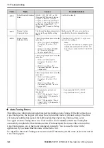
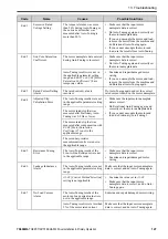
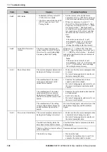
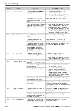
Page 88: ...neral Purpose 2 Intelligent Ignore Decel Ramp 3 General Purpose w DB resistor 4 Overexcitation High Flux 5 Overexcitation High Flux 2 7 Overexcitation High Flux 3 13 Troubleshooting If the drive or motor do not operate correctly look at the drive keypad for fault and alarm information For drive faults The keypad shows the fault code ALM ERR LED stays illuminated The drive shuts off output and the ...

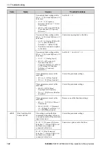
Page 89: ... high the regeneration power or repetition frequency is high Install a regenerative converter Increase the deceleration time You enabled the protective function for the braking transistor when you have a regenerative converter Set L8 55 0 Internal DB TransistorProtection Selection Disable The braking transistor in the drive is broken Replace the drive bUS Option Communication Error The drive did n...

Page 90: ...the controller side or the drive input power side Separate the communication wiring from drive power lines and install a noise filter to the input side of the power supply for communication Decrease the effects of electrical interference from the controller CF Control Fault Motor parameters are set incorrectly Correctly set the motor parameters and do Auto Tuning again The torque limit setting is ...

Page 91: ...ause of the fault CPF00 CPF01 CPF02 CPF03 CPF08 CPF11 CPF14 CPF16 CPF24 CPF38 Control Circuit Error A drive hardware problem occurred Re energize the drive If the fault stays replace the control board or the drive For information about replacing the control board contact Yaskawa or your nearest sales representative CPF06 EEPROM Memory Data Error The drive power supply was de energized while a comm...

Page 92: ...am and remove the cause of the fault This is not a drive fault dWF3 DriveWorksEZ Fault 3 There was a fault in the DriveWorksEZ program Examine the DriveWorksEZ program and remove the cause of the fault This is not a drive fault dWFL DriveWorksEZ Fault There was a fault in the DriveWorksEZ program Examine the DriveWorksEZ program and remove the cause of the fault This is not a drive fault E5 MECHAT...

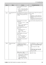
Page 93: ...3 but the terminal is not in use Correctly set the MFDI EF4 External Fault Terminal S4 MFDI terminal S4 caused an external fault through an external device 1 Find the device that caused the external fault and remove the cause 2 Clear the external fault input in the MFDI The wiring is incorrect Correctly connect the signal line to MFDI terminal S4 External Fault H1 04 20 to 2B is set to MFDI termin...

Page 94: ...dback input circuit of the drive Replace the control board or the drive For information about replacing the control board contact Yaskawa or your nearest sales representative FbL PID Feedback Loss The FbL detection level is set incorrectly Adjust b5 13 PID Feedback Loss Detection Lvl and b5 14 PID Feedback Loss Detection Time There is a problem with the PID feedback wiring Correct errors with the ...

Page 95: ...cing the control board contact Yaskawa or your nearest sales representative LF2 Output Current Imbalance Phase loss occurred in the wiring on the output side of the drive Examine for wiring errors or disconnected wires on the output side of the drive and repair problems The output terminal screws of the drive are loose Tighten the terminal screws to the correct tightening torque There is not balan...

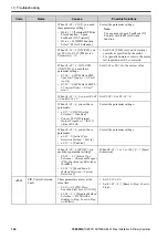
Page 96: ...mmand while the Node Setup function was active Stop the drive when the Node Setup function is in use oC Overcurrent The load is too heavy Measure the current flowing into the motor Replace the drive with a larger capacity model if the current value is more than the drive rated current Decrease the load or replace with a larger drive to prevent sudden changes in the current level Overheating caused...

Page 97: ...ern frequency and voltage Decrease the voltage if it is too high compared to the frequency Adjust E1 04 to E1 10 V f Pattern Parameters For motor 2 adjust E3 04 to E3 10 The torque compensation gain is too large Decrease the value set in C4 01 Torque Compensation Gain to make sure that the motor does not stall Electrical interference caused a problem Examine the control circuit lines main circuit ...

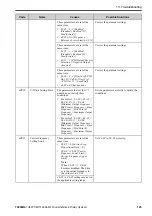
Page 98: ...ppression Level oC2 Overcurrent2 When A1 02 5 6 8 Control Method Selection OLV PM AOLV PM or EZOLV the output current is more than the value set in L8 27 Overcurrent Detection Gain Correct the value set in L8 27 oFA00 Option Not Compatible with Port The option connected to connector CN5 is not compatible Connect a correct option oFA01 Option Fault Connection Error You changed the option card conne...

Page 99: ...sure the output current Decrease the load Decrease the value set in C6 02 Carrier Frequency Selection The internal cooling fan of the drive stopped 1 Use the procedures in this manual to replace the cooling fan 2 Set o4 03 0 Fan Operation Time Setting 0 h oH1 Heatsink Overheat The ambient temperature is high and the heatsink temperature of the drive is more than the oH1 detection level Measure the...

Page 100: ...lt PTC Input The motor has overheated Check the load level acceleration deceleration time and motor start stop frequency cycle time Decrease the load Increase the values set in C1 01 to C1 08 Acceleration Deceleration Times Set E2 01 Motor Rated Current FLA correctly to the value specified by the motor nameplate Make sure that the motor cooling system is operating correctly and repair or replace i...

Page 101: ...0 are too low the overload tolerance will decrease at low speeds E1 06 Base Frequency is set incorrectly Set E1 06 to the rated frequency shown on the motor nameplate One drive is operating more than one motor Set L1 01 0 Motor Overload oL1 Protection Disabled connect thermal overload relay to each motor to prevent damage to the motor The electronic thermal protector qualities and the motor overlo...

Page 102: ...tput Voltage For motor 2 adjust E3 04 to E3 10 Note If the values set in E1 08 and E1 10 are too low the overload tolerance will decrease at low speeds The drive capacity is too small Replace the drive with a larger capacity model Overload occurred while running at low speed Decrease the load when running at low speed Replace the drive with a larger capacity model Decrease the value set in C6 02 C...

Page 103: ...Slip Braking Use a braking resistor to decrease the deceleration time The value set in n3 04 HSB Overload Time is too small Increase the value set in n3 04 Connect a thermal overload relay to the motor and set n3 04 1200 s maximum value oPr Keypad Connection Fault The keypad is not securely connected to the connector on the drive Examine the connection between the keypad and the drive The connecti...

Page 104: ... drive through the power supply 1 Examine the motor main circuit cable terminals and motor terminal box and then remove ground faults 2 Re energize the drive The speed search related parameters are set incorrectly this fault also occurs during recovery from momentary power loss and after Auto Restarts Examine the settings for all speed search related parameters Set b3 19 0 Speed Search Restart Att...

Page 105: ...oltage is changing too much Examine the input power for problems Make the drive input power stable If the input power supply is good examine the magnetic contactor on the main circuit side for problems There is unsatisfactory balance between voltage phases Examine the input power for problems Make the drive input power stable Set L8 05 0 Input Phase Loss Protection Sel Disabled The main circuit ca...

Page 106: ...acing the control board contact Yaskawa or your nearest sales representative SC Short Circuit IGBT Failure Overheating caused damage to the motor or the motor insulation is not satisfactory Measure the motor insulation resistance and replace the motor if there is electrical conduction or unserviceable insulation The motor main circuit cable is contacting ground to make a short circuit Examine the ...

Page 107: ...crease the load Replace the drive and motor with larger capacity models The load inertia is too large Increase the value set in n8 55 The acceleration deceleration times are too short Increase the values set in C1 01 to C1 08 Acceleration Deceleration Times Increase the value set in C2 01 S Curve Time Start of Accel Speed response is too slow Increase the value set in n8 55 TiM Keypad Time Not Set...

Page 108: ... the soft charge bypass relay If U4 06 is more than 90 replace the board or the drive For information about replacing the board contact Yaskawa or your nearest sales representative Uv2 Control Power Undervoltage The value set in L2 02 Power Loss Ride Through Time increased and the momentary power loss recovery unit is not connected to the drive Connect the momentary power loss recovery unit to the...

Page 109: ...m 32 8 ft or nearer to the keypad Note bCE can occur when the smartphone or tablet is 10 m or nearer to the keypad depending on the specifications of the smartphone or tablet Radio waves from a different device are causing interference with the communication between the smartphone or tablet and keypad Make sure that no device around the keypad uses the same radio bandwidth 2400 MHz to 2480 MHz and...

Page 110: ...ce the option card CALL Serial Comm Transmission Error The communications cable wiring is incorrect Correct wiring errors There is a short circuit in the communications cable or the communications cable is not connected Repair the short circuited or disconnected portion of the cable Replace the defective communications cable A programming error occurred on the controller side Examine communication...

Page 111: ...roblem Examine the controller and remove the cause of the problem CP1 Comparator 1 Limit Error The monitor value set in H2 20 Comparator 1 Monitor Selection was in the range of H2 21 Comparator 1 Lower Limit and H2 22 Comparator 1 Upper Limit Examine the monitor value and remove the cause of the fault CP2 Comparator 2 Limit Error The monitor value set in H2 26 Comparator 2 Monitor Selection was ou...

Page 112: ...effects of electrical interference as specified by these manuals MECHATROLINK II Installation Guide MECHATROLINK Members Association manual number MMATDEP011 MECHATROLINK III Installation Manual MECHATROLINK Members Association publication number MMATDEP018 EF FWD REV Run Command Input Error A forward command and a reverse command were input at the same time for longer than 0 5 s Examine the forwa...

Page 113: ...4 but the terminal is not in use Correctly set the MFDI EF5 External Fault Terminal S5 MFDI terminal S5 caused an external fault through an external device 1 Find the device that caused the external fault and remove the cause 2 Clear the external fault input in the MFDI The wiring is incorrect Correctly connect the signal line to MFDI terminal S5 External Fault H1 05 2C to 2F is set to MFDI termin...

Page 114: ...he control device side A fault occurred in the feedback input circuit of the drive Replace the board or the drive For information about replacing the control board contact Yaskawa or your nearest sales representative HCA High Current Alarm The load is too heavy Decrease the load for applications with repetitive starts and stops Replace the drive with a larger capacity model The acceleration time i...

Page 115: ... at 90 of expected performance life Replace the board or the drive For information about replacing the control board contact Yaskawa or your nearest sales representative LT 3 SoftChargeBypassRe lay MainteTime The soft charge bypass relay is at 90 of its expected performance life Replace the board or the drive For information about replacing the control board contact Yaskawa or your nearest sales r...

Page 116: ... values set in E1 08 Mid Point A Voltage and E1 10 Minimum Output Voltage Note If the values set in E1 08 and E1 10 are too low the overload tolerance will decrease at low speeds oL3 Overtorque 1 A fault occurred on the machine Example The machine is locked Examine the machine and remove the cause of the fault The parameters are incorrect for the load Adjust L6 02 Torque Detection Level 1 and L6 0...

Page 117: ...h the drive rated voltage Electrical interference caused a drive malfunction Examine the control circuit lines main circuit lines and ground wiring and decrease the effects of electrical interference Make sure that a magnetic contactor is not the source of the electrical interference then use a Surge Protective Device if necessary Set L5 01 0 Number of Auto Restart Attempts 0 times PASS Modbus Com...

Page 118: ...rminals H1 HC or H2 HC When the Safe Disable function is not in use use a jumper to connect terminals H1 HC and H2 HC There is internal damage to one Safe Disable channel Replace the board or the drive For information about replacing the control board contact Yaskawa or your nearest sales representative TiM Keypad Time Not Set There is a battery in the keypad but the date and time are not set Set ...

Page 119: ...the drive For information about replacing the control board contact Yaskawa or your nearest sales representative The drive input power transformer is too small and voltage drops when the power is switched on Check for an alarm when a molded case circuit breaker Leakage Breaker ELCB GFCI or RCM RCD with overcurrent protective function or magnetic contactor is ON Check the capacity of the drive powe...

Page 120: ... No Load Current Make sure that E2 01 E2 03 Note If it is necessary to set E2 01 E2 03 first lower the value set in E2 03 and then set E2 01 oPE03 Multi Function Input Setting Err The settings for these parameters do not agree H1 01 to H1 07 Terminals S1 to S8 Function Selection H7 01 to H7 04 Virtual Multi Function Inputs 1 to 4 Correct the parameter settings The settings for MFDIs overlap Note T...

Page 121: ...etting values 61 Speed Search from Fmax and 62 Speed Search from Fref Setting values 65 66 7A 7B KEB Ride Thru 1 or 2 Activate and 68 High Slip Braking HSB Activate Setting values 16 Motor 2 Selection and 1A Accel Decel Time Selection 2 Setting values 65 66 KEB Ride Thru 1 Activate and 7A 7B KEB Ride Thru 2 Activate Setting values 40 41 Forward RUN 2 Wire Reverse RUN 2 Wire and 42 43 Run Command 2...

Page 122: ...n Selection Frequency Reference Set H3 02 0 or H3 10 0 These parameters are set at the same time H1 xx 6A Drive Enable H2 xx 38 Drive Enabled Correct the parameter settings These parameters are set at the same time H6 01 3 PG Speed Feedback V F Control H1 xx 7E Reverse Rotation Identifier Correct the parameter settings These parameters are set at the same time H1 xx 75 76 Up 2 Down 2 Command H3 01...

Page 123: ... Feedback Value These parameters are set at the same time H3 02 H3 10 H7 30 C PID Setpoint H6 01 2 PID Setpoint Value These parameters are set at the same time H3 02 H3 10 H7 30 C b5 18 1 PID Setpoint Selection Enabled These parameters are set at the same time H6 01 2 b5 18 1 Remove the function settings that are not in use oPE08 Parameter Selection Error A function was set that is not compatible ...

Page 124: ...k EMF L L Vrms mV rpm 0 0 mV min 1 Set E5 09 or E5 24 to the correct value When A1 02 5 6 you set E5 09 0 and E5 24 0 Set E5 09 0 or E5 24 0 When A1 02 6 you set these parameters n8 57 0 HFI Overlap Selection Disabled You set E1 09 Minimum Output Frequency the 5 value of E1 06 Correct the parameter settings When A1 02 6 you set these parameters n8 35 0 Initial Pole Detection Method Pull in n8 57 1...

Page 125: ... V f Data Setting Error The parameters that set the V f pattern do not satisfy these conditions For motor 1 E1 09 E1 07 E1 06 E1 11 E1 04 Minimum Output Frequency Mid Point A Frequency Base Frequency Mid Point B Frequency Maximum Output Frequency For motor 2 E3 09 E3 07 E3 06 E3 11 E3 04 Minimum Output Frequency Mid Point A Frequency Base Frequency Mid Point B Frequency Maximum Output Frequency Se...

Page 126: ...nction Not Used H2 03 1xx Term P2 Function Selection Inverse output of xx Clear the H2 01 to H2 03 1xx Inverse output of xx settings Note If you use the function to output logical calculation results H2 60 H2 63 H2 66 F you cannot set H2 01 to H2 03 1xx These parameter pairs are set incorrectly H2 21 Comparator 1 Lower Limit H2 22 Comparator 1 Upper Limit H2 27 Comparator 2 Lower Limit H2 28 Compa...

Page 127: ... Adjusted Slip Calculation Error The Auto Tuning results were not in the applicable parameter setting range The motor rated slip that was measured after Stationary Auto Tuning was 0 2 Hz or lower The motor rated slip that was measured after compensation with E2 08 Motor Saturation Coefficient 2 is not in the applicable range The secondary resistor measurement results were not in the applicable ran...

Page 128: ...necessary Er 01 Motor Data Error The motor nameplate data entered during Auto Tuning is incorrect Make sure that the motor nameplate data is correct Do Auto Tuning again and correctly set the motor nameplate data The combination of the motor rated power and motor rated current do not match Examine the combination of drive capacity and motor output Do Auto Tuning again and correctly set the motor r...

Page 129: ...ate data entered during Auto Tuning is incorrect Make sure that the input motor nameplate data is correct Do Auto Tuning again and correctly set the motor nameplate data Rotational Auto Tuning was done with a load that was more than 30 of the rating connected to the motor Disconnect the machine from the motor and do Rotational Auto Tuning again If you cannot uncouple the motor and load make sure t...

Page 130: ...al Auto Tuning again Er 11 Motor Speed Error The torque reference during acceleration is too high 100 Increase the value set in C1 01 Acceleration Time 1 Disconnect the machine from the motor and do Rotational Auto Tuning again Er 12 Current Detection Error There is a phase loss in the drive input power U T1 V T2 W T3 Examine and repair motor wiring The current exceeded the current rating of the d...

Page 131: ...f the drive cannot rotate the motor in reverse 1 Enable reverse in the target machine 2 Set b1 04 0 Reverse Enabled 3 Do Inertia Tuning again Er 18 Back EMF Error The result of the induced voltage tuning was not in the applicable range 1 Make sure that the input motor nameplate data is correct 2 Do Auto Tuning again and correctly set the motor nameplate data Er 19 PM Inductance Error The Auto Tuni...

Page 132: ... in this section show the error codes If there are errors refer to these tables Note Push any key on the keypad to clear an error Code Name Causes Possible Solutions CPEr Control Mode Mismatch The keypad setting and drive setting for A1 02 Control Method Selection do not agree 1 Set A1 02 on the drive to the same value that is on the keypad 2 Restore the parameters CPyE Error Writing Data Paramete...

Page 133: ...rs in the drive are not the same 1 Restore or backup the parameter again 2 Verify the parameters 14 European Standards Figure 14 1 CE Mark The CE Mark identifies that the product meets environmental and safety standards in the European Union Products manufactured sold or imported in the European Union must display the CE Mark European Union standards include standards for electrical appliances Low...

Page 134: ...plies with the CE Low Voltage Directive by conducting a test according to EN 61800 5 1 2007 The following conditions must be satisfied for machines and devices incorporating this product to comply with the CE Low Voltage Directive Area of Use Install this product in a location with Overvoltage Category III and pollution degree 2 or less as specified in IEC CE 60664 Guarding Against Debris When you...

Page 135: ... can cause damage to the drive and serious injury or death from fire 2 For circuit protection the main circuit is separated from the surface case that can touch the main circuit 3 The control circuit is a Safety Extra Low Voltage circuit Separate this circuit from other circuits with reinforced insulation Make sure that the Safety Extra Low Voltage circuit is connected as specified 4 Reinforced in...

Page 136: ...or options are out of the range of the applicable gauges for the drive Wire Selection Precautions WARNING Electrical Shock Hazard Make sure that the protective ground wire complies with technical standards and local safety regulations The EN 61800 5 1 2007 standard specifies that you must wire the power supply to automatically de energize when the protective ground wire disconnects If you turn on ...

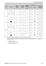
Page 137: ... Stripping Length 1 mm Terminal Screw Tightening Torque N m in lb Size Shape B001 L L1 N L2 2 5 2 5 6 5 M3 0 5 0 6 4 4 5 3 U T1 V T2 W T3 2 5 2 5 6 5 M3 0 5 0 6 4 4 5 3 1 2 5 2 5 6 5 M3 0 5 0 6 4 4 5 3 B1 B2 2 5 2 5 6 5 M3 0 5 0 6 4 4 5 3 2 5 2 2 5 2 M3 5 0 8 1 0 7 1 8 9 B002 L L1 N L2 2 5 2 5 6 5 M3 0 5 0 6 4 4 5 3 U T1 V T2 W T3 2 5 2 5 6 5 M3 0 5 0 6 4 4 5 3 1 2 5 2 5 6 5 M3 0 5 0 6 4 4 5 3 B1 ...

Page 138: ...0 6 4 4 5 3 1 2 5 2 5 6 5 M3 0 5 0 6 4 4 5 3 B1 B2 2 5 2 5 6 5 M3 0 5 0 6 4 4 5 3 2 5 2 2 5 2 M3 5 0 8 1 0 7 1 8 9 B006 L L1 N L2 2 5 2 5 4 8 M3 0 5 0 6 4 4 5 3 U T1 V T2 W T3 2 5 2 5 4 8 M3 0 5 0 6 4 4 5 3 1 2 5 2 5 4 8 M3 0 5 0 6 4 4 5 3 B1 B2 2 5 2 5 4 8 M3 0 5 0 6 4 4 5 3 2 5 2 2 5 6 2 M4 1 2 1 5 10 6 13 3 B010 L L1 N L2 2 5 2 5 4 8 M3 0 5 0 6 4 4 5 3 U T1 V T2 W T3 2 5 2 5 4 8 M3 0 5 0 6 4 4 ...

Page 139: ...5 10 6 13 3 B018 L L1 N L2 6 2 5 10 10 M4 1 5 1 7 13 5 15 U T1 V T2 W T3 2 5 2 5 4 10 M4 1 5 1 7 13 5 15 1 6 2 5 10 10 M4 1 5 1 7 13 5 15 B1 B2 2 5 2 5 4 10 M4 1 5 1 7 13 5 15 6 2 4 10 2 M5 2 0 2 5 17 7 22 1 1 Remove insulation from the ends of wires to expose the length of wire shown 2 If you turn on the internal EMC filter the leakage current of the drive will be more than 3 5 mA Use these close...

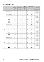
Page 140: ... M3 0 5 0 6 4 4 5 3 1 2 2 5 2 5 6 5 M3 0 5 0 6 4 4 5 3 B1 B2 2 5 2 5 6 5 M3 0 5 0 6 4 4 5 3 2 5 2 2 5 2 M3 5 0 8 1 0 7 1 8 9 2002 R L1 S L2 T L3 2 5 2 5 6 5 M3 0 5 0 6 4 4 5 3 U T1 V T2 W T3 2 5 2 5 6 5 M3 0 5 0 6 4 4 5 3 1 2 2 5 2 5 6 5 M3 0 5 0 6 4 4 5 3 B1 B2 2 5 2 5 6 5 M3 0 5 0 6 4 4 5 3 2 5 2 2 5 2 M3 5 0 8 1 0 7 1 8 9 2004 R L1 S L2 T L3 2 5 2 5 6 5 M3 0 5 0 6 4 4 5 3 U T1 V T2 W T3 2 5 2 5...

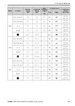
Page 141: ...4 4 5 3 1 2 2 5 2 5 6 5 M3 0 5 0 6 4 4 5 3 B1 B2 2 5 2 5 6 5 M3 0 5 0 6 4 4 5 3 2 5 2 2 5 2 M3 5 0 8 1 0 7 1 8 9 2010 R L1 S L2 T L3 2 5 2 5 4 8 M3 0 5 0 6 4 4 5 3 U T1 V T2 W T3 2 5 2 5 4 8 M3 0 5 0 6 4 4 5 3 1 2 2 5 2 5 4 8 M3 0 5 0 6 4 4 5 3 B1 B2 2 5 2 5 4 8 M3 0 5 0 6 4 4 5 3 4 2 2 5 6 2 M4 1 2 1 5 10 6 13 3 2012 R L1 S L2 T L3 2 5 2 5 4 8 M3 0 5 0 6 4 4 5 3 U T1 V T2 W T3 2 5 2 5 4 8 M3 0 5 ...

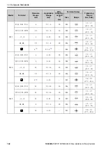
Page 142: ... 1 7 13 5 15 1 2 6 4 10 10 M4 1 5 1 7 13 5 15 B1 B2 2 5 2 5 4 10 M4 1 5 1 7 13 5 15 6 2 2 5 6 2 M4 1 2 1 5 10 6 13 3 2030 R L1 S L2 T L3 6 4 10 10 M4 1 5 1 7 13 5 15 U T1 V T2 W T3 6 4 10 10 M4 1 5 1 7 13 5 15 1 2 10 2 5 16 10 M4 1 5 1 7 13 5 15 B1 B2 2 5 2 5 4 10 M4 1 5 1 7 13 5 15 6 2 6 16 M5 2 0 2 5 17 7 22 1 2042 R L1 S L2 T L3 10 2 5 16 10 M4 1 5 1 7 13 5 15 U T1 V T2 W T3 10 2 5 16 10 M4 1 5...

Page 143: ...16 6 25 20 M6 5 5 5 45 49 1 2 35 10 50 20 M6 5 5 5 45 49 B1 B2 10 4 16 10 M4 1 5 1 7 13 5 15 16 10 25 M6 5 4 6 0 47 8 53 1 2082 R L1 S L2 T L3 35 10 50 20 M6 5 5 5 45 49 U T1 V T2 W T3 25 10 35 20 M6 5 5 5 45 49 1 2 50 16 70 20 M6 5 5 5 45 49 B1 B2 16 4 16 10 M4 1 5 1 7 13 5 15 16 10 25 M6 5 4 6 0 47 8 53 1 1 Remove insulation from the ends of wires to expose the length of wire shown 2 If you turn...

Page 144: ...3 0 5 0 6 4 4 5 3 1 2 2 5 2 5 4 8 M3 0 5 0 6 4 4 5 3 B1 B2 2 5 2 5 4 8 M3 0 5 0 6 4 4 5 3 2 5 2 2 5 6 2 M4 1 2 1 5 10 6 13 3 4002 R L1 S L2 T L3 2 5 2 5 4 8 M3 0 5 0 6 4 4 5 3 U T1 V T2 W T3 2 5 2 5 4 8 M3 0 5 0 6 4 4 5 3 1 2 2 5 2 5 4 8 M3 0 5 0 6 4 4 5 3 B1 B2 2 5 2 5 4 8 M3 0 5 0 6 4 4 5 3 2 5 2 2 5 6 2 M4 1 2 1 5 10 6 13 3 4004 R L1 S L2 T L3 2 5 2 5 4 8 M3 0 5 0 6 4 4 5 3 U T1 V T2 W T3 2 5 2...

Page 145: ...4 4 5 3 1 2 2 5 2 5 4 8 M3 0 5 0 6 4 4 5 3 B1 B2 2 5 2 5 4 8 M3 0 5 0 6 4 4 5 3 4 2 2 5 6 2 M4 1 2 1 5 10 6 13 3 4007 R L1 S L2 T L3 2 5 2 5 4 8 M3 0 5 0 6 4 4 5 3 U T1 V T2 W T3 2 5 2 5 4 8 M3 0 5 0 6 4 4 5 3 1 2 2 5 2 5 4 8 M3 0 5 0 6 4 4 5 3 B1 B2 2 5 2 5 4 8 M3 0 5 0 6 4 4 5 3 4 2 2 5 6 2 M4 1 2 1 5 10 6 13 3 4009 R L1 S L2 T L3 2 5 2 5 4 8 M3 0 5 0 6 4 4 5 3 U T1 V T2 W T3 2 5 2 5 4 8 M3 0 5 ...

Page 146: ... 7 13 5 15 1 2 2 5 2 5 4 10 M4 1 5 1 7 13 5 15 B1 B2 2 5 2 5 4 10 M4 1 5 1 7 13 5 15 4 2 2 5 6 2 M4 1 2 1 5 10 6 13 3 4018 R L1 S L2 T L3 2 5 2 5 4 10 M4 1 5 1 7 13 5 15 U T1 V T2 W T3 2 5 2 5 4 10 M4 1 5 1 7 13 5 15 1 2 4 2 5 6 10 M4 1 5 1 7 13 5 15 B1 B2 2 5 2 5 4 10 M4 1 5 1 7 13 5 15 4 2 2 5 16 M5 2 0 2 5 17 7 22 1 4023 R L1 S L2 T L3 4 2 5 6 10 M4 1 5 1 7 13 5 15 U T1 V T2 W T3 4 2 5 6 10 M4 ...

Page 147: ...5 1 7 13 5 15 1 2 10 2 5 16 18 M5 2 3 2 5 19 8 22 B1 B2 2 5 2 5 4 10 M4 1 5 1 7 13 5 15 6 2 6 16 2 M6 5 4 6 0 47 8 53 1 4038 R L1 S L2 T L3 10 4 16 10 M4 1 5 1 7 13 5 15 U T1 V T2 W T3 6 2 5 10 10 M4 1 5 1 7 13 5 15 1 2 16 4 25 18 M5 2 3 2 5 19 8 22 B1 B2 4 2 5 6 10 M4 1 5 1 7 13 5 15 10 6 16 M6 5 4 6 0 47 8 53 1 4044 R L1 S L2 T L3 16 4 25 18 M5 2 3 2 5 19 8 22 U T1 V T2 W T3 10 4 16 18 M5 2 3 2 ...

Page 148: ...R8 4S from NICHIFU Co Ltd P10 8R from PANDUIT Corp Connect a Fuse to the Input Side Primary Side The drive circuit protection must comply with EN 61800 5 1 2007 for protection against a short circuit in the internal circuitry Connect semiconductor fuses on the input side for branch circuit protection Refer to Single Phase 200 V Class on page 149 Three Phase 200 V Class on page 149 and Three Phase ...

Page 149: ...odel Semiconductor Protection Fuse Rated Current Manufacturer EATON Bussmann 2001 FWH 25A14F 2002 FWH 25A14F 2004 FWH 25A14F 2006 FWH 25A14F 2010 FWH 70B 2012 FWH 70B Drive Model Semiconductor Protection Fuse Rated Current Manufacturer EATON Bussmann 2021 FWH 90B 2030 FWH 100B 2042 FWH 150B 2056 FWH 200B 2070 FWH 200B 2082 FWH 225A Three Phase 400 V Class Table 14 5 Factory Recommended Branch Circ...

Page 150: ...se for each drive when operating more than one drive If one fuse blows replace all fuses Install the external filter system to comply with the EMC Directive Refer to Table 14 6 Table 14 7 and Table 14 8 for the recommended fuses Table 14 6 Recommended Fuse Single Phase 200 V Class Drive Model Fuse Manufacturer Bussmann Model B001 FWH 25A14F B002 FWH 25A14F B004 FWH 60B B006 FWH 80B Drive Model Fus...

Page 151: ... Bussmann Model 4018 FWH 80B 4023 FWH 100B 4031 FWH 125B 4038 FWH 175B 4044 FWH 200B 4060 FWH 200B EMC Directive Use drives with built in EMC filters or install external EMC filters to the drive input side to comply with the EMC Directive Drives with built in EMC filters models BxxxE 2xxxE 4xxxE were tested in accordance with European standard EN 61800 3 2004 A1 2012 and comply with the EMC Direct...

Page 152: ...otor is BxxxE 10 m 32 8 ft 2xxxE 4xxxE 20 m 65 6 ft Note Use a braided shield cable for the drive and motor wiring or put the wires through a metal conduit Keep the cable between the drive and motor and the grounding wire as short as possible 4 Use a cable clamp to ground the motor cable to the metal plate Note Make sure that the protective ground wire complies with technical specifications or loc...

Page 153: ...n page 161 to select a DC link choke Note To comply with EN 61000 3 2 on drive models 2001 to 2006 and 4001 to 4004 install a DC link choke The terminal block for the drive main circuit and the terminal block for the DC link choke have different shapes The drive has a European style terminal block and the DC link choke has a round terminal block Correctly prepare the ends of the wiring Ground Wiri...

Page 154: ... covers or touch circuit boards while the drive is energized If you touch the internal components of an energized drive it can cause serious injury or death WARNING Electrical Shock Hazard Ground the neutral point on the power supply of drive models BxxxE 2xxxE and 4xxxE to comply with the EMC Directive before you turn on the EMC filter or if there is high resistance grounding If you turn ON the E...

Page 155: ...the corner of the delta connection Grounded at the middle of the side Single phase grounded at the end point Three phase variable transformer without solidly grounded neutral Table 14 10 EMC Filter Switch Location Model Switch Location Diagram B001E B004E 2001E 2006E Figure 14 8 B006E B012E 2010E 2021E 4001E 4012E Figure 14 9 2030E 2082E 4018E 4060E Figure 14 10 ...

Page 156: ...European Standards 156 YASKAWA TOEPC71061752B GA500 Drive Installation Primary Operation A SW ON B SW OFF Figure 14 8 EMC Filter Switch Location 1 A SW ON B SW OFF Figure 14 9 EMC Filter Switch Location 2 ...

Page 157: ...001 2006 M3 16 0 5 0 7 4 4 6 2 B006 B012 2010 2021 4001 4012 M3 20 0 5 0 7 4 4 6 2 2030 2082 4018 4060 M4 20 1 0 1 3 8 9 11 5 Installing the External EMC Noise Filter Drive models BxxxA 2xxxA and 4xxxA must align with the conditions in this section to comply with EN 61800 3 2004 A1 2012 Connect an EMC noise filter that complies with European standards as specified by Yaskawa to the input side prim...

Page 158: ...he drive and motor wiring or put the wires through a metal conduit Keep the wire as short as possible The maximum wiring length between the drive and motor is BxxxA 2xxxA 4xxxA 10 m 32 8 ft Keep the grounding wire as short as possible 4 Use a cable clamp to ground the motor cable to the metal plate Note Make sure that the protective ground wire complies with technical specifications or local safet...

Page 159: ...tion Refer to DC Link Chokes on page 161 to select a DC link choke Note To comply with EN 61000 3 2 on drive models 2001 to 2006 and 4001 to 4004 install a DC link choke The terminal block for the drive main circuit and the terminal block for the DC link choke have different shapes The drive has a European style terminal block and the DC link choke has a round terminal block Correctly prepare the ...

Page 160: ... 20 07 1 Schaffner B010 FS23638 20 07 1 Schaffner B012 FS23638 30 07 1 Schaffner B018 FS23638 40 07 1 Schaffner Table 14 13 External EMC Noise Filter 2xxxA Drive model EMC Noise Filter Model Quantity Manufacturer 2001 FS23637 8 07 1 Schaffner 2002 FS23637 8 07 1 Schaffner 2004 FS23637 8 07 1 Schaffner 2006 FS23637 8 07 1 Schaffner 2010 FS23637 14 07 1 Schaffner 2012 FS23637 14 07 1 Schaffner 2021 ...

Page 161: ... 4031 FS5972 60 07 1 1 Schaffner 4038 FS5972 60 07 1 1 Schaffner 4044 RTEN 5100 1 TDK 4060 RTEN 5100 1 TDK 1 When you install an external EMC noise filter change the terminals or use the junction terminal DC Link Chokes To comply with EN 61000 3 2 drive models 2001 to 2006 and 4001 to 4004 install a DC link choke when you use an internal or external EMC filter Refer to Table 14 15 to select a DC l...

Page 162: ...s product in a location with Overvoltage Category III and pollution degree 2 or less as specified in UL61800 5 1 Ambient Temperature Setting Maintain the ambient temperature within the following ranges according to the enclosure type IP20 UL Type 1 10 C to 40 C 14 F to 104 F IP20 UL Open Type 10 C to 50 C 14 F to 122 F Wire the Main Circuit Terminal Block Wire the main circuit terminal block corre...

Page 163: ...the range of the applicable gauges for the drive Wire Selection Precautions WARNING Electrical Shock Hazard Make sure that the protective ground wire complies with technical standards and local safety regulations The EN 61800 5 1 2007 standard specifies that you must wire the power supply to automatically de energize when the protective ground wire disconnects If you turn on the internal EMC filte...

Page 164: ...WG kcmil Wire Stripping Length 1 mm Terminal Screw Tightening Torque N m in lb Size Shape B001 L L1 N L2 14 14 6 5 M3 0 5 0 6 4 4 5 3 U T1 V T2 W T3 14 14 6 5 M3 0 5 0 6 4 4 5 3 1 14 14 6 5 M3 0 5 0 6 4 4 5 3 B1 B2 14 14 6 5 M3 0 5 0 6 4 4 5 3 14 2 14 2 M3 5 0 8 1 0 7 1 8 9 B002 L L1 N L2 14 14 6 5 M3 0 5 0 6 4 4 5 3 U T1 V T2 W T3 14 14 6 5 M3 0 5 0 6 4 4 5 3 1 14 14 6 5 M3 0 5 0 6 4 4 5 3 B1 B2 ...

Page 165: ...5 M3 0 5 0 6 4 4 5 3 1 14 14 6 5 M3 0 5 0 6 4 4 5 3 B1 B2 14 14 6 5 M3 0 5 0 6 4 4 5 3 14 2 14 2 M3 5 0 8 1 0 7 1 8 9 B006 L L1 N L2 12 14 10 8 M3 0 5 0 6 4 4 5 3 U T1 V T2 W T3 14 14 12 8 M3 0 5 0 6 4 4 5 3 1 12 14 10 8 M3 0 5 0 6 4 4 5 3 B1 B2 14 14 12 8 M3 0 5 0 6 4 4 5 3 10 2 14 10 2 M4 1 2 1 5 10 6 13 3 B010 L L1 N L2 10 12 10 8 M3 0 5 0 6 4 4 5 3 U T1 V T2 W T3 14 14 12 8 M3 0 5 0 6 4 4 5 3 ...

Page 166: ... 2 1 5 10 6 13 3 B018 L L1 N L2 8 12 6 10 M4 1 5 1 7 13 5 15 U T1 V T2 W T3 10 14 8 10 M4 1 5 1 7 13 5 15 1 8 12 6 10 M4 1 5 1 7 13 5 15 B1 B2 14 14 12 10 M4 1 5 1 7 13 5 15 8 2 12 8 2 M5 2 0 2 5 17 7 22 1 1 Remove insulation from the ends of wires to expose the length of wire shown 2 If you turn on the internal EMC filter the leakage current of the drive will be more than 3 5 mA Use these closed ...

Page 167: ...W T3 14 14 6 5 M3 0 5 0 6 4 4 5 3 1 2 14 14 6 5 M3 0 5 0 6 4 4 5 3 B1 B2 14 14 6 5 M3 0 5 0 6 4 4 5 3 14 2 14 2 M3 5 0 8 1 0 7 1 8 9 2002 R L1 S L2 T L3 14 14 6 5 M3 0 5 0 6 4 4 5 3 U T1 V T2 W T3 14 14 6 5 M3 0 5 0 6 4 4 5 3 1 2 14 14 6 5 M3 0 5 0 6 4 4 5 3 B1 B2 14 14 6 5 M3 0 5 0 6 4 4 5 3 14 2 14 2 M3 5 0 8 1 0 7 1 8 9 2004 R L1 S L2 T L3 14 14 6 5 M3 0 5 0 6 4 4 5 3 U T1 V T2 W T3 14 14 6 5 M...

Page 168: ... 5 0 6 4 4 5 3 1 2 14 14 6 5 M3 0 5 0 6 4 4 5 3 B1 B2 14 14 6 5 M3 0 5 0 6 4 4 5 3 14 2 14 2 M3 5 0 8 1 0 7 1 8 9 2010 R L1 S L2 T L3 14 14 12 8 M3 0 5 0 6 4 4 5 3 U T1 V T2 W T3 14 14 12 8 M3 0 5 0 6 4 4 5 3 1 2 12 14 10 8 M3 0 5 0 6 4 4 5 3 B1 B2 14 14 12 8 M3 0 5 0 6 4 4 5 3 10 2 14 10 2 M4 1 2 1 5 10 6 13 3 2012 R L1 S L2 T L3 12 14 10 8 M3 0 5 0 6 4 4 5 3 U T1 V T2 W T3 12 14 10 8 M3 0 5 0 6 ...

Page 169: ...1 7 13 5 15 1 2 8 14 8 10 M4 1 5 1 7 13 5 15 B1 B2 14 14 10 10 M4 1 5 1 7 13 5 15 8 14 8 M4 1 2 1 5 10 6 13 3 2030 R L1 S L2 T L3 8 12 6 10 M4 1 5 1 7 13 5 15 U T1 V T2 W T3 8 12 6 10 M4 1 5 1 7 13 5 15 1 2 6 12 6 10 M4 1 5 1 7 13 5 15 B1 B2 12 12 8 10 M4 1 5 1 7 13 5 15 8 10 6 M5 2 0 2 5 17 7 22 1 2042 R L1 S L2 T L3 6 12 6 10 M4 1 5 1 7 13 5 15 U T1 V T2 W T3 6 12 6 10 M4 1 5 1 7 13 5 15 1 2 4 1...

Page 170: ...3 2 8 1 20 M6 5 5 5 45 49 1 2 1 6 1 0 20 M6 5 5 5 45 49 B1 B2 8 12 6 10 M4 1 5 1 7 13 5 15 4 6 4 M6 5 4 6 0 47 8 53 1 2082 R L1 S L2 T L3 1 6 1 0 20 M6 5 5 5 45 49 U T1 V T2 W T3 2 6 1 20 M6 5 5 5 45 49 1 2 2 0 2 2 0 20 M6 5 5 5 45 49 B1 B2 6 10 6 10 M4 1 5 1 7 13 5 15 4 6 4 M6 5 4 6 0 47 8 53 1 1 Remove insulation from the ends of wires to expose the length of wire shown 2 If you turn on the inte...

Page 171: ...4 12 8 M3 0 5 0 6 4 4 5 3 1 2 14 14 12 8 M3 0 5 0 6 4 4 5 3 B1 B2 14 14 12 8 M3 0 5 0 6 4 4 5 3 14 2 14 10 2 M4 1 2 1 5 10 6 13 3 4002 R L1 S L2 T L3 14 14 12 8 M3 0 5 0 6 4 4 5 3 U T1 V T2 W T3 14 14 12 8 M3 0 5 0 6 4 4 5 3 1 2 14 14 12 8 M3 0 5 0 6 4 4 5 3 B1 B2 14 14 12 8 M3 0 5 0 6 4 4 5 3 14 2 14 10 2 M4 1 2 1 5 10 6 13 3 4004 R L1 S L2 T L3 14 14 12 8 M3 0 5 0 6 4 4 5 3 U T1 V T2 W T3 14 14 ...

Page 172: ...5 0 6 4 4 5 3 1 2 14 14 12 8 M3 0 5 0 6 4 4 5 3 B1 B2 14 14 12 8 M3 0 5 0 6 4 4 5 3 10 2 14 10 2 M4 1 2 1 5 10 6 13 3 4007 R L1 S L2 T L3 14 14 12 8 M3 0 5 0 6 4 4 5 3 U T1 V T2 W T3 14 14 12 8 M3 0 5 0 6 4 4 5 3 1 2 14 14 12 8 M3 0 5 0 6 4 4 5 3 B1 B2 14 14 12 8 M3 0 5 0 6 4 4 5 3 10 2 14 10 2 M4 1 2 1 5 10 6 13 3 4009 R L1 S L2 T L3 14 14 12 8 M3 0 5 0 6 4 4 5 3 U T1 V T2 W T3 14 14 12 8 M3 0 5 ...

Page 173: ... 5 1 7 13 5 15 1 2 10 12 8 10 M4 1 5 1 7 13 5 15 B1 B2 14 14 12 10 M4 1 5 1 7 13 5 15 10 2 14 10 2 M4 1 2 1 5 10 6 13 3 4018 R L1 S L2 T L3 10 12 8 10 M4 1 5 1 7 13 5 15 U T1 V T2 W T3 10 12 8 10 M4 1 5 1 7 13 5 15 1 2 10 14 8 10 M4 1 5 1 7 13 5 15 B1 B2 14 14 12 10 M4 1 5 1 7 13 5 15 10 2 14 6 2 M5 2 0 2 5 17 7 22 1 4023 R L1 S L2 T L3 8 14 6 10 M4 1 5 1 7 13 5 15 U T1 V T2 W T3 10 14 8 10 M4 1 5...

Page 174: ...4031 R L1 S L2 T L3 8 12 6 10 M4 1 5 1 7 13 5 15 U T1 V T2 W T3 8 12 6 10 M4 1 5 1 7 13 5 15 1 2 6 12 4 18 M5 AWG 10 2 3 2 5 19 8 22 AWG 8 4 1 4 5 36 40 B1 B2 10 12 8 10 M4 1 5 1 7 13 5 15 8 10 6 M6 5 4 6 0 47 8 53 1 4038 R L1 S L2 T L3 6 12 6 10 M4 1 5 1 7 13 5 15 U T1 V T2 W T3 8 12 6 10 M4 1 5 1 7 13 5 15 1 2 4 10 2 18 M5 AWG 10 2 3 2 5 19 8 22 AWG 8 4 1 4 5 36 40 B1 B2 10 14 6 10 M4 1 5 1 7 13...

Page 175: ...3 5 15 6 10 6 M6 5 4 6 0 47 8 53 1 1 Remove insulation from the ends of wires to expose the length of wire shown 2 If you turn on the internal EMC filter the leakage current of the drive will be more than 3 5 mA Use these closed loop crimp terminals or equivalent to connect a protective ground wire that has a minimum cross sectional area of 10 mm2 copper wire 8 4NS from JST Mfg Co Ltd R8 4S from N...

Page 176: ...mended Branch Circuit Protection Single Phase 200 V Class Drive Model Maximum Applicable Motor Output kW HP Time Delay Fuse Semiconductor Protection Fuse Rated Current Manufacturer EATON Bussmann ND HD Class J CC and T Fuse Rated Current A Model Fuse Rated Current A B001 0 2 1 6 0 1 1 6 2 FWH 25A14F 25 B002 0 4 1 4 0 2 1 4 3 5 FWH 25A14F 25 B004 0 75 3 4 0 4 1 2 9 FWH 60B 60 B006 1 1 1 5 0 75 1 15...

Page 177: ... 400 V Class Table 15 4 Factory Recommended Branch Circuit Protection Three Phase 400 V Class Drive Model Maximum Applicable Motor Output kW HP Time Delay Fuse Semiconductor Protection Fuse Rated Current Manufacturer EATON Bussmann ND HD Class J CC and T Fuse Rated Current A Model Fuse Rated Current A 4001 0 4 1 2 0 2 1 2 3 FWH 40B 40 4002 0 75 1 0 4 3 4 3 5 FWH 40B 40 4004 1 5 2 0 75 2 7 FWH 50B ...

Page 178: ...wer supply in the drive Use the UL Listed class 2 power supply for external power supply Pulse Train Input RP AC Uses the LVLC power supply in the drive Use the UL Listed class 2 power supply for external power supply Safe disable input H1 H2 HC Uses the LVLC power supply in the drive Use the UL Listed class 2 power supply for external power supply Serial communication input output D D AC Uses the...

Page 179: ...ame Description Default Range E5 03 032B Motor Rated Current FLA Sets the PM motor rated current FLA Determined by o2 04 C6 01 10 to 200 of the drive rated current Note When the drive model changes the display units for this parameter also change 0 01 A B001 to B018 2001 to 2042 4001 to 4023 0 1 A 2056 to 2082 4031 to 4060 The drive automatically sets E5 03 to the value input for T2 06 PM Motor Ra...

Page 180: ... characteristics of the motor to select motor protection The electronic thermal protector of the drive uses these items to calculate motor overload tolerance and supply overload protection for the motor Output Current Output Frequency Motor thermal characteristics Time characteristics If the drive detects motor overload the drive will trigger an oL1 Motor Overload and stop the drive output Set H2 ...

Page 181: ...s at 100 motor load This motor is designed to operate with commercial line power Operate at a 60 Hz base frequency to maximize the motor cooling ability If the motor operates at frequencies less than 60 Hz the drive will detect oL1 The drive triggers a fault relay output and the motor coasts to stop 2 Constant Torque 10 1 Speed Range Use this setting for drive dedicated motors with a speed range f...

Page 182: ...ge Load Tolerance Cooling Capability Overload Characteristics at 100 motor load This motor is designed to withstand increased temperatures during continuous operation at rated speed and rated torque If the motor operates continuously at lower speed than rated rotation speed at more than 100 torque the drive will detect oL1 The drive triggers a fault relay output and the motor coasts to stop 5 PM C...

Page 183: ... 02 0481 Motor Overload Protection Time Sets the operation time for the electronic thermal protector of the drive to prevent damage to the motor Usually it is not necessary to change this setting 1 0 min 0 1 5 0 min Set the overload tolerance time to the length of time that the motor can operate at 150 load from continuous operation at 100 load When the motor operates at 150 load continuously for ...

Page 184: ...tivates 1 Coast to Stop The output turns off and the motor coasts to stop The output terminal set for Fault H2 01 to H2 03 E activates 2 Fast Stop The drive stops the motor in the deceleration time set in C1 09 Fast Stop Time The output terminal set for Fault H2 01 to H2 03 E activates 3 Alarm Only The keypad shows oH3 and the drive continues operation The output terminal set for Alarm H2 01 to H2...

Page 185: ...014 which were promulgated on January 26 2016 The number displayed in the center of the mark indicates the environment friendly use period number of years in which electrical and electronic products that are being produced sold or imported to China can be used The date of manufacture of the electrical and electronic product is the starting date of the environment friendly use period for the produc...

Page 186: ...used for this part is above the limit requirement of GB T 26572 Note This product complies with EU RoHS directives In this table indicates that hazardous substances that are exempt from EU RoHS directives are contained 17 对应中国RoHS指令 图 17 1 中国RoHS标志 中国RoHS标志依据2016年1月26日公布的 电器电子产品有害物质限制使用管理办法 以 及 电子电气产品有害物质限制使用标识要求 SJ T 11364 2014 作成 电子电气产品中 特定6种有害物质的含量超过规定值时 应标识此标志 中间的数字为在中国生产销售以及进 口的电子电气产品的环保使用期限 ...

Page 187: ...2005 A2 2015 SILCL3 IEC 61800 5 2 2016 SIL3 EN 61800 5 2 2017 SIL3 Machine Safety ISO EN ISO 13849 1 2015 Cat 3 PL e EMC IEC 61000 6 7 2014 EN 61000 6 7 2015 IEC EN 61326 3 1 2017 LVD IEC 61800 5 1 2007 AMD1 2016 EN 61800 5 1 2007 A1 2017 Note SIL Safety Integrity Level Safe Disable Specifications The Safe Disable input provides the stop function that complies with Safe Torque Off as specified by ...

Page 188: ...o a full risk assessment for the system to make sure that all parts of the system comply with applicable safety standards Incorrect application of the Safe Disable function can cause serious injury or death DANGER Sudden Movement Hazard If the output circuit of the drive is damaged and the Safe Disable function turns OFF the drive output to a permanent magnet PM motor the motor can rotate 180 elec...

Page 189: ...nd all other safety features A system that does not operate correctly can cause serious injury or death WARNING Sudden Movement Hazard Only let approved personnel who know about the drive instruction manual and safety standards wire examine and maintain the Safe Disable input If personnel are not approved it can cause serious injury or death WARNING Sudden Movement Hazard Only use the Safe Disable...

Page 190: ... Multiple Drives To Use the Drive Internal Power Supply An example of connecting Safe Disable contacts is shown in Figure 18 3 From the terminals HC SN of drive 1 supply the power for the Safe Disable function for the applicable drives These conditions limit the number of units to connect Internal power supply capacity Number of MFDIs used Supply current to the external sensors ...

Page 191: ...acts is shown in Figure 18 4 These conditions limit the number of units to connect External power supply capacity Number of MFDIs used Supply current to the external sensors HC Drive 1 SN H1 H2 E G HC Drive 2 SN H1 H2 E G HC Drive 3 SN H1 H2 E G S1 S2 Open Safety switch Safety controller Reset feedback input Safety Electronic Device Monitor output Connect MFDO terminals set to Safe Torque OFF H2 x...

Page 192: ...ives to Connect Power Supply Digital Inputs 24 V Output Number of Drives Internal power supply Drive 1 Yes 7 channel input Yes 1 1 No 13 No Yes 1 4 No 17 External power supply Different for different external power supply capacities 2 1 This is when you use a maximum of 150 mA 2 24 V 12 mA is necessary for each drive Use this formula to calculate the number of units to connect ...

Page 193: ... Safe Disable function When the Safe Disable function is enabled while the motor is operating the drive output and motor torque turn off and the motor always coasts to stop The b1 03 Stopping Method Selection setting does not have an effect on the stopping method The Safe Torque Off status is only possible with the Safe Disable function Clear the Run command to stop the drive Turning off drive out...

Page 194: ... ALM ERR Flashing 1 0 ON Close the circuit OFF Open OFF ON Safety status STo SToF Flashing ALM ERR Flashing 1 0 OFF Open OFF Open ON OFF Safety status STo STo Flashing READY Flashing 0 1 Safety Function Status Monitor The drive Safety monitor output sends a feedback signal about the status of the Safety function The Safety monitor output is one of the possible settings available for the MFDO termi...

Page 195: ...FF status of the MFDO may not display correctly on the keypad Incorrect parameter settings A problem with an external device The external wiring has a short circuit or is disconnected There is damage to the device Find the cause and repair the problem to correctly display the status 3 Make sure that the EDM signal operates during usual operation as shown in Table 18 3 19 Disposal Disposal Instruct...

Page 196: ...061752B GA500 Drive Installation Primary Operation Revision History Date of Publication Revision Number Section Revised Content August 2019 1 All Revision Reviewed and corrected entire documentation May 2019 First Edition ...

Page 197: ...YASKAWA TOEPC71061752B GA500 Drive Installation Primary Operation 197 ...

Page 198: ...ttp www yaskawa eu com YASKAWA ELÉTRICO DO BRASIL LTDA 777 Avenida Piraporinha Diadema São Paulo 09950 000 Brasil Phone 55 11 3585 1100 Fax 55 11 3585 1187 http www yaskawa com br In the event that the end user of this product is to be the military and said product is to be employed in any weapons systems or the manufacture thereof the export will fall under the relevant regulations as stipulated ...

Reviews: