


Yaskawa Electric America, Inc. –
IG.V7.26, Page 2 of 11
Date: 05/24/2010 Rev: 10-05
V7 EtherNet/IP Option Kit
CM093
11. Diagnostic LED power up test sequence
A power-up test is performed each time the V7 drive is powered up after the
initial boot sequence. The initial boot sequence may take several seconds.
When this sequence is complete, the LEDs will assume normal conditions.
The
EtherNet/IP Option Kit
is successfully initialized after the LEDs have
completed the above sequence.
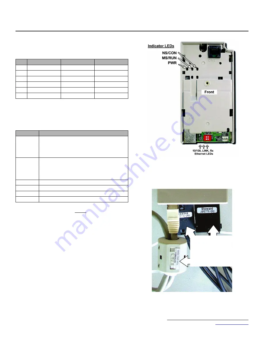
12. LED descriptions
The
EtherNet/IP Option Kit
LED status after the power-up sequence is described
below. Please wait at least five seconds for the loading process to complete before
verifying the status of the LEDs.
13. Connect to the
V7 EtherNet/IP Option Kit
Note:
It is strongly recommended that shielded CAT-5 cable be used.
a. Connect to the Ethernet network.
1.
Direct connection:
To connect directly to the
V7 EtherNet/IP
Option Kit
, plug one end of a shielded CAT-5
crossover
cable into
the RJ-45 socket on the
V7 EtherNet/IP Option Kit
. Connect the
other end to the RJ-45 Ethernet socket on the configuration device,
typically a controller, laptop or other PC.
2.
Connection through hub or switch:
To connect through a switch,
hub or router, connect
V7 EtherNet/IP Option Kit
to the switch, hub
or router using a standard shielded CAT-5 patch cable.
b.
Loop the CAT-5 Ethernet cable through the provided ferrite
(Intermark RFC-13) and connect the ferrite as close to the RJ-45
connection as possible. Secure the ferrite to the Ethernet cable with the
provided cable tie. If the ferrite cannot be mounted in your installation
please contact Yaskawa for application assistance. See the figure in the
lower right corner of this page.
c.
Attach the provided ferrites
to the V7 drive motor and power leads as
close to the V7 drive terminals as possible (typically within 1 foot).
Secure the ferrites to the motor and power leads with the provided cable
ties. See the figure to the right.
Successful Initialization:
The
V7 EtherNet/IP Option Kit
hardware is installed and operating correctly with
the LEDs in the states shown in
bold text
in the "LED Descriptions" table. The
LINK LED represents the status of the physical connection to the network and is
not indicative of any card state.
Application of Ferrites:
Seq
MS/RUN
NS/CON
Time
1
GREEN
OFF
250ms
2
RED
OFF
250ms
3
GREEN
OFF
250ms
4
GREEN
GREEN
250ms
5
GREEN
RED
250ms
6
GREEN
OFF
Seq
MS/RUN
MS/RUN
GREEN – Card Functioning Normally
GREEN BLINK – Standby/Initializing (500ms cycle)
RED BLINK – Minor Fault (500ms cycle)
RED – Major Fault
GREEN/RED BLINK – Module Test (500ms cycle)
NS/CON
GREEN – Connected
GREEN BLINK – Waiting for Connections (500ms cycle)
RED BLINK – Connection Timeout (500ms cycle)
RED – Duplicate IP Address
GREEN/RED BLINK – Network Test (500ms cycle)
10/100
GREEN – 100Mbs Connection Speed
LINK
GREEN – Link Established
Rx
GREEN – Message Being Received
PWR
GREEN – Appropriate Power Supplied to Card
Ferrites around power
and motor leads
Ferrite around looped
CAT5 Ethernet cable


