


4
-12
3. Perform autotuning.
After having completed autotuning, set E1-04 (Max. output frequency) to the base frequency shown on the
motor nameplate.
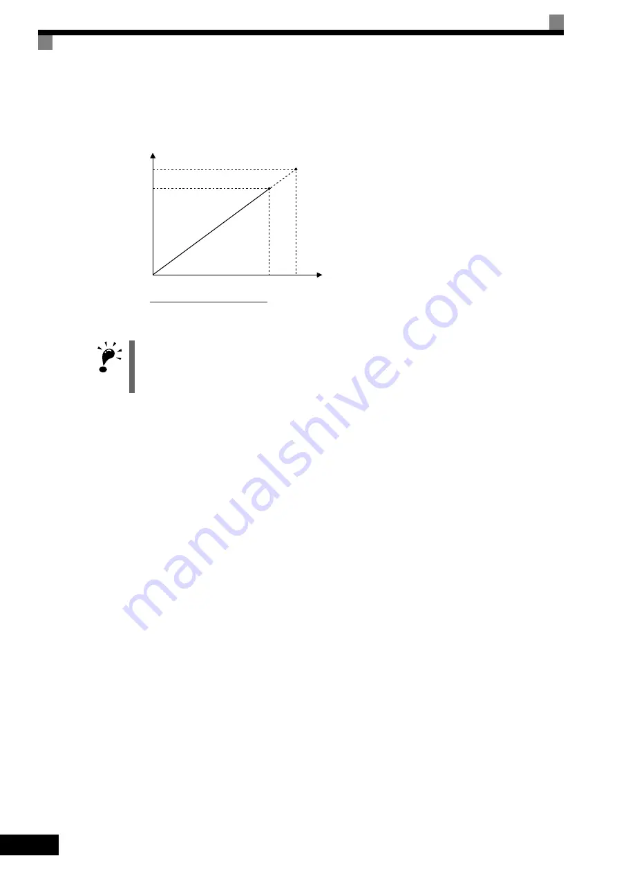
Fig 4.4 Motor Base Frequency and Inverter Input Voltage Setting
Precautions after Using Rotational and Stationary Autotuning
After completing autotuning, set E1-04 (Max. output frequency) to the base frequency from the motor’s name-
plate.
In stationary autotuning1, when the motor is first operated in the drive mode after tuning, the remaining motor
constants E2-02 (Motor rated slip) and E2-03 (Motor no-load current) are set automatically. To perform an
operation immediately after stationary autotuning 1, use the following procedure under the recommended con-
ditions.
1. Check the values of E2-02 and E2-03 in verify mode or advanced programming mode.
2. Run the motor once in drive mode under the following conditions.
•
The Inverter and the motor are connected.
•
The motor shaft is not locked with a mechanical brake or other stopping mechanism (or function).
•
A motor-load ratio of 30% or less is maintained.
•
A speed of 30% or more of the base frequency set at E1-06 (default = highest frequency) is main-
tained at a constant speed for one second or more.
3. After stopping the motor, check the values of E2-02 and E2-03 again in verify mode or advanced pro-
gramming mode. If the values of E2-02 and E2-03 differ from the ones before the first operation was
carried out, the settings have been successfully completed. Next, check if the values are suitable or not.
If the values of E2-02 and E2-03 differed greatly from the reference data of the motor in the test report or
the instruction manual, hunting, motor vibrations, insufficient motor torque, or an overcurrent may occur
because the motor is operated although the aforementioned conditions have not been fulfilled after station-
ary autotuning 1. For elevators, failure to observe this caution may result in the cage falling or injury. If
so, perform stationary autotuning 1 again and run the motor using the aforementioned procedure under the
recommended conditions or perform stationary autotuning 2 or rotational autotuning.
Usually the standard setting for E2-02 is 1Hz to 3Hz, and that for E2-03 is 30% to 65% of the rated current
for a general-purpose motor. Generally, the larger the motor capacity is, the smaller the rated slip and the
ratio of the no-load current to the rated current become. Use the data given in
Factory Settings that
Change with the Inverter Capacity (o2-04)
of
Chapter 5 User Constants
as a reference.
IMPORTANT
1. When speed precision is required at high speeds (i.e., 90% of the rated speed or higher), set T1-03 (Motor
rated voltage) to the input power supply voltage
×
0.9.
2. When operating at high speeds (i.e., 90% of the rated speed or higher), the output current will increase as
the input power supply voltage is reduced. Be sure to provide sufficient margin in the Inverter current.
Output voltage
Output frequency
Rated voltage from
motor nameplate
T1-03
0
Rated voltage from motor nameplate
Base frequency
from motor nameplate
×
T1-03
Base frequency
from motor nameplate


