
model no.
060-1300-6
| contact us: 1.866.523.5218
model no.
060-1300-6
| contact us: 1.866.523.5218
47
M
AINT
eNANC
e
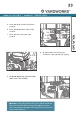
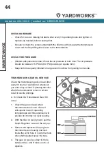
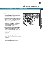
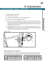
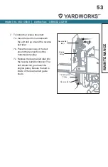
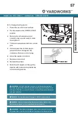
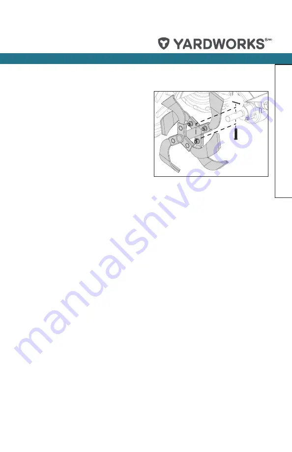
C. Removing/Installing a Tine Assembly:
1. A tine assembly consists of eight tines
mounted on a tine holder.
2. If removing both tine assemblies, mark
them “left” and “right” before removal.
Remove (2) pins and (2) cotter pins
that secure the tine assembly to the
tine shaft. If necessary, use a rubber
mallet to tap the tine assembly
outward off the shaft.
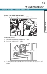
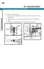
3. Before reinstalling the tine assembly,
inspect the tine shaft for rust, rough
spots or burrs. Lightly file or sand, as
needed. Apply a thin coat of grease to
the shaft.
4. Install each tine assembly so that the
cutting (sharp) edge of the tines will
enter the soil first when the tiller moves
forward.
5. Bend cotter pins once inserted to
prevent the pins from coming out.
Summary of Contents for 060-1300-6
Page 63: ...model no 060 1300 6 contact us 1 866 523 5218 63 PAGE INTENTIONALLY LEFT BLANK...
Page 65: ...model no 060 1300 6 contact us 1 866 523 5218 65 EXPLODED VIEW PRODUCT...
Page 66: ...model no 060 1300 6 contact us 1 866 523 5218 66 EXPLODED VIEW PRODUCT...
Page 67: ...model no 060 1300 6 contact us 1 866 523 5218 67 EXPLODED VIEW PRODUCT...
Page 73: ...model no 060 1300 6 contact us 1 866 523 5218 73 PAGE INTENTIONALLY LEFT BLANK...