background image

V III. Storage

[8-1.] Storing

Whenever the engine will not be used for several months, use the following procedure to
properly store it.
This minimizes corrosion and deterioration.

1) Drain fuel completely from fuel tank, otherwise moisture from the fuel system will mix
with the fuel.

2) Wash the cooling system with clean tap water and drain out the cooling water from the
engine completely.

2-a)
Cylinder body

2-b) Exhaust manifold.

2-c)
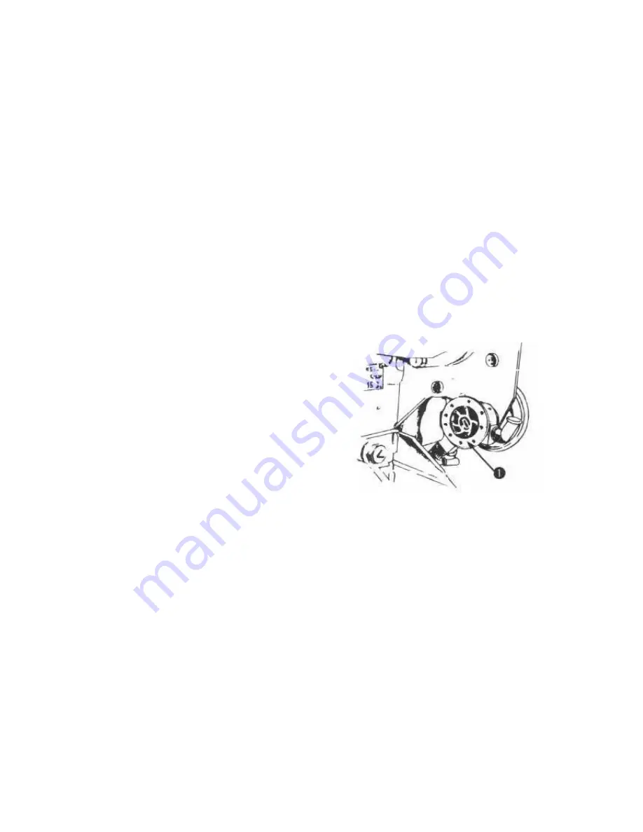
Cooling water pump Remove the cover of the
cooling water pump and drain out the water inside of
the cooling water pump.

3) Apply an anti-rust oil to any parts which rust
easily.

4) Since the battery will automatically discharge
itself if left, disconnect when fully charged, wash the
exterior and store in a dry, well-aired place.
Re-charge once a month during storage.

1. Cooling water pump

5) Tape to seal air inlet, exhaust pipe, and fuel tank cap.

6) Clean the engine throughly. Touch up any painted surfaces that are scratched or chipped.

7) If boat must be stored outside, cover it with waterproof material.

[82.] Removing engine from storage

1) Wipe off anti-rust oil and check that the remote control system move smoothly.

2) Wiring the battery.

2-a) Rewire as shown in the wiring diagram.

2-b) Make sure wires are connected to the correct terminals.

Summary of Contents for 1GM

Page 1: ...Yan...

Page 2: ...uality and performance engine parts may sometimes be changed This may result in some discrepancies in the contents of this manual This manual is concerned with the 2 cylinder model Although the 1GM 3G...

Page 3: ...ct parts to you we need accurate data on the engine you purchased The information needed is described in the illustrations below For ready reference please record the information in the spaces provide...

Page 4: ......

Page 5: ...10 Mixing elbow 11 Air intake silencer 12 Alternator 13 Lube oil filter 14 Starter motor 15 Decompression lever 16 Anticorrosion zinc 17 Fuel injection pump 18 Fuel injection valve 19 Crankshaft V pu...

Page 6: ......

Page 7: ...ion angle will differ with the vessel configuration and installation location of the engine The most suitable installation angle is 8 degrees and the maximum installation angle is 15 degrees If it is...

Page 8: ...of the engine with a jack nut to line up the propeller shaft and the engine Fit the propeller shaft and the intermediate shaft if there is one to the engine With a gap gauge measure the gap of the co...

Page 9: ...engine should be operated only after checking the cooling water piping is completed Important If the Cooling water pump is operated without water the rubber impeller inside the pump will be broken 2...

Page 10: ...e layout Be sure to use the water lock Installation of piping should be done as shown in the following diagram 6 a In case the water outlet of the engine side A is above water line 6 b In case the wat...

Page 11: ...1 Seawater pump 2 Seawater strainer 3 Kingston cock 1 W L 2 Waterlock 3 Above seawater line 1 W L 2 Waterlock 3 Vacuum valve...

Page 12: ...metal fittings Speed Control Morse 33 C Yanmar Standard Yanmar Standard Clutch Control Morse 33 C Yanmar Standard Yanmar Standard Engine Stop option Yanmar made Morse 2 Speed control 2 a A spring is a...

Page 13: ...ch for 1GM 2GM 3GMD 3 a 1 Remove the spring joint from the operation lever 3 a 2 With the spring joint disconnected from the operation lever move the operation lever forward and reverse to make sure t...

Page 14: ...position the output shaft propeller shaft of the clutch should rotate clockwise as viewed from the stern 3 a 5 Move the remote control lever to the reverse position and make sure that the M5 thread o...

Page 15: ...ntrol and the shift lever on the marine gearbox work properly A typical linkage arrangement is illustrated in the figure below 1 Astern 4 Propeller side 2 Neutral 5 Engine Side 3 Ahead Note Since the...

Page 16: ...1 Clamp 2 Engine Stop lever 3 Engine stop remote control cable 3 7 Recommended battery capacity Use sufficient capacity of battery 1GM 2GM 3GMD 12V 70AH Mini 3HM 12V 100AH Mini...

Page 17: ...elative compression can be determined by comparing the weight re sistance when turning of the clutch handle when placed in the neutral ahead and astern positions When there is little weight difference...

Page 18: ...on use grade No 1 D diesel fuel as defined in ASTM Designation D975 with a pour point at least 5 6 C 10 F below the lowest outside air temperature 1 d The cetane number should be 40 minimum Low atmosp...

Page 19: ...starting and running performance The lube oil weight number chosen should vary with the season and temperature 4 Recommended brands of lube oil for crankcase SAE NO SAE NO SAE NO SUPPLIER BRAND TEMP...

Page 20: ...nted materials floating on the fuel surface or depositing in the bottom 2 Draining the fuel tank Be sure to equip the fuel tank with a precipitation tank as shown in the figure and install a drain coc...

Page 21: ...st time the tube oil flows to the piping thus reducing the amount of oil in the crankcase After running the engine for several minutes stop it for 2 3 minutes Recheck the oil level 2 Lube oil to the r...

Page 22: ...1 Dipstick 2 Empty 3 Full 1 Oil Supply Port 1 Oil Gauge Rod 2 Lower Limit 3 Upper Limit...

Page 23: ...he engine warm up knob change the control lever from the speed decrease position to the speed increase position Check the slippage of the position on the bridge and in the engine room and adjust as ne...

Page 24: ...2 Charge 3 L O Press 4 Push Button 5 Warning buzzer 6 Key switch 2 Cooling water temperature warning lamp Should be out for small type panel A type only For the large type panel B type raise the CHEC...

Page 25: ...pen the kingston cock 4 Turn on the battery switch insert the key into the switch and turn it to ON FOR 1GM 5 Push the starter button and simultaneously pull the STOP wire turn the engine over 5 10 ti...

Page 26: ...1 Push Button DIRECTION OF ROTATION...

Page 27: ...area especially areas where there are revolving parts 3 Full Speed 1 Neutral 2 Slow Speed 7 1 Starting 1 Electric starting 1 Warm up knob 1 a Pull out the engine warm up knob and place the control le...

Page 28: ...M 3HM Note In cold weather When starting is difficult in cold weather raise the decompression handle to the no compression position and turn the starter motor over After the engine gains momentum retu...

Page 29: ...ll the decompression lever down to the compression position Turn two or three times without stopping and the engine will start 2 e After starting return control lever from FULL SPEED to SLOW SPEED 7 2...

Page 30: ...opped Lube oil lamp ON OFF ON Pressure down Cooling water lamp OFF OFF ON Temp rise Charge lamp ON OFF ON No charge Warning buzzer BUZZ OFF BUZZ Above trouble Except no charge If any of the warning la...

Page 31: ...r shaft Consult your nearest dealer if the temperature of the engine parts is too high 6 Exhaust smoke The emission of black exhaust smoke indicates that the engine is being overworked If so operated...

Page 32: ...e 1a Place the clutch handle in the neutral position and idle the engine for about 5 minutes Important If the engine is stopped suddenly while at a high temperature the tem perature of various parts w...

Page 33: ...n out the cooling water In winter and in periods of col d weather when there is the possibility that the cooling water may freeze the cooling water should be drained out after use 3 a Open up the cyli...

Page 34: ...warm wipe off any dirt and grime that has accumulated 5 Turn off the battery switch Note When stopping the engine with the starter switch ON the tube oil pressure warning buzzer will sound This does...

Page 35: ...ooling water pump 3 Apply an anti rust oil to any parts which rust easily 4 Since the battery will automatically discharge itself if left disconnect when fully charged wash the exterior and store in a...

Page 36: ...C generator may break 2 c Terminals must be covered and protected 3 Unseal all openings sealed in step 1 5 4 Also observe points in section IV Starting the new engine for the first time For an ever b...

Page 37: ......

Page 38: ......

Page 39: ...ean the fuel tank cap and blow dry periodically 2 Air bleeding in the fuel system If air enters any part of the system with the exception of the fuel tank fuel will not be injected into the cylinders...

Page 40: ...nder pressure can have sufficient force to penetrate the skin causing serious personal injury Before disconnecting lines be sure to relieve all pressure in the system be sure no connections are damage...

Page 41: ...knob out and place the control lever in the half speed position 3 d Rotate the engine to check the fuel injection timing At the same time the arrow timing mark on the cylinder block and flywheel shoul...

Page 42: ...block side timing mark 2 Flywheel 3 Crankshaft pulley 4 M8 bolt 3 f Remove the fuel injection nozzle and check the injection spray condition Cone shaped condition is proper If the spray is not cone sh...

Page 43: ...r motor 4 Washing and replacement of the fuel filter element Remove the lower cover of the fuel filter and wash or replace the element 1 Fuel Filter The proper method to remove the element is shown in...

Page 44: ...ld be drained from the crankcase by moving the handle of the oil evacuation pump forward and backward 2 Oil Evacuation pump optional 1 c Replace the lube oil filter Replace the lube oil filter every 3...

Page 45: ...gine lube oil Important Reduction reversing gear case oil for 3GMD and 3HM is different from engine lube oil 9 3 Cooling water system 1 Make sure that water is coming out of the cooling water outlet p...

Page 46: ...the cooling water pump 3 a 1 Remove the cooling water pump cover take out the impeller and check for damage to the impeller and mechanical seal parts If damaged replace with a new one 1 Cover 2 Packi...

Page 47: ...the cooling water pump drive belt If there is too much tension premature damage to the V belt will occur On the other hand of the V belt pulley is loose it will slip and cooling water flow will be in...

Page 48: ...GHTENING TORQUE 1GM MAIN M10 7 5 kg m 2GM 3GMD MAIN M12 10 kg m SUB M8 2 5 kg m 3HM MAIN M12 13 kg m SUB M8 3 kg m 2 Exhaust intake valve head clearance adjustment The clearance of the valve will affe...

Page 49: ...learance to the maintenance standard with a thickness gauge and retighten the lock nut In the case of 2 cylinder model adjust the valve head clearance of the No 2 cylinder in the same manner after tur...

Page 50: ...w fill to bottom of filler neck with distilled water 2 d To check battery condition use a battery hydrometer Check specific gravity of electrolyte in each cell Charge battery if reading is below 1 215...

Page 51: ...cable too much Adjustment of idling engine speed The idling sped is generally set at 850 900 rpm In case the idling speed is too low adjust the following way Loosen the lock nut and turn the diling ad...

Page 52: ...nd Neutral to Reverse B are nearly same If the strokes are not the same see your nearest Yanmer dealer 1 Astern 2 Ahead 2 b Checking the spring joint condition With connecting the spring joint to the...

Page 53: ...retighten all nuts and bolts securely Caution 1 Always stop the engine when inspect and maintain the control cable 2 Be carefully when conduct inspection and maintenance imi ediately after stopping t...

Page 54: ......

Page 55: ......

Page 56: ......

Reviews: