background image

VE2711-1-8,VE2711-2-8F,VE2713-2-8F,VE2740PR-1-8F,VE2740PR-2-8F
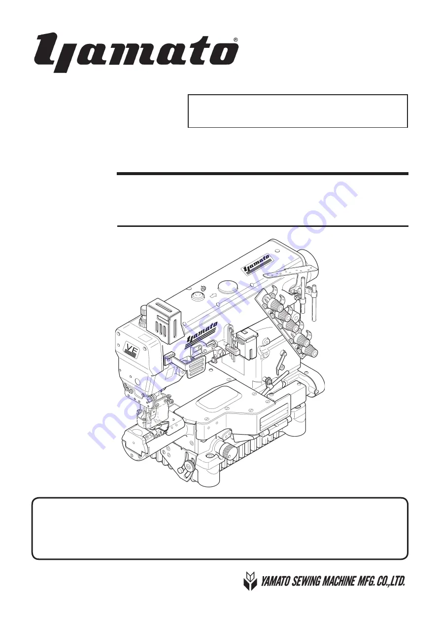
VE2700-8 class

HIGH SPEED SMALL CYLINDER BED INTERLOCK STITCH MACHINE 

Instruction Manual

Thank you for purchasing VE2700-8 class. Before using your VE2700-8 class, please read the 
instruction manual and understand the contents well. 
After reading the instruction manual, please keep it in a location where it is easily accessible 
to the operator.

Summary of Contents for VE2700-8 class

Page 1: ...R BED INTERLOCK STITCH MACHINE Instruction Manual Thank you for purchasing VE2700 8 class Before using your VE2700 8 class please read the instruction manual and understand the contents well After rea...

Page 2: ...rection of the pulley 9 4 Lubrication 10 4 1 Lubricating oil 10 4 2 Lubricating 10 4 3 Changing oil 11 4 4 Checking and replacing the oil filter 11 5 Proper operation 12 5 1 Needle system 12 5 2 Insta...

Page 3: ...9 2 Needle guard front 31 6 10 Height of the feed dog 32 6 11 Removing the presser foot and presser foot lift 33 6 12 Toeing up and down the presser foot 34 6 13 Adjusting the walking presser foot VE2...

Page 4: ...r any third party mishandles the machine or does not avoid the dangerous situation when operating or maintaining the machine CAUTION This indication is given when there is a potential danger of medium...

Page 5: ...ents If any of the labels has become stained or come unstuck be sure to replace it with a new one 2 2 Working environment The environment in which our industrial sewing machines are used may seriously...

Page 6: ...ns after verifying that the machine has stopped completely since the motor continues turning for a while even after turning off the power supply switch 3 PRECAUTIONS TO BE TAKEN IN VARIOUS OPERATING S...

Page 7: ...operly as required by law If you have further questions on its disposal consult the place of purchase After opening the oil container be sure to seal it to prevent dust and water from getting into the...

Page 8: ...the power supply switch when terminating the sewing work or leaving the sewing machine In the event of the power failure be sure to turn off the power Also if the sewing machine malfunctions makes ab...

Page 9: ...the eye guard opened Finger guard The finger guard prevents the operator s fingers from going under the needle However there is some space at the top of the finger guard and other sections and so the...

Page 10: ...ntation and 3 To be prepared with the above technical documentation compiled in accordance with part B of Annex VII and 4 Relevant information on wish should be transmitted in response to a reasoned r...

Page 11: ...ight window Presser spring regulator Finger guard Adjusting knob Eye guard Looper thread take up Belt cover small Needle bar guard Thread tension spring cap Needle thread take up guard Feed graduation...

Page 12: ...The circled dimensions are required only for models with UT device Fig 2 1 Refer to the instruction manual of the motor for dimensions A B C and D Section X X Section Y Y Center of pulley Operator 3...

Page 13: ...dimensions are required only for models with UT device Fig 2 2 Section X X Table dimensions 1200 595 50 Center of pulley 3 9 5 Installing hole for motor Operator Refer to the instruction manual of th...

Page 14: ...Semi submerged type Section X X 1 2 Section Z Z 1 2 Center of pulley 3 9 5 Installing hole for motor Operator Table dimensions 1200 595 50 Fig 2 3 Refer to the instruction manual of the motor for dime...

Page 15: ...emi submerged type Fig 2 7 Fig 2 6 Fig 2 5 Install the machine correctly referring to Figs 2 4 2 5 Install the machine correctly referring to Figs 2 6 2 7 Fig 2 4 Sewing machine Machine table Sewing m...

Page 16: ...Numbers in is calculated values Table 2 V belt of M type 5 5 10 40 Servomotor Use a servomotor with an output of 500 W or more Calculate the outside diameter of a motor pulley from the formula as bel...

Page 17: ...m being caught by the belt Table top type 2 5 Hanging the belt Use a V belt of M type 1 Hang the belt on the machine pulley and then on the motor pulley while turning the machine pul ley 2 Adjust the...

Page 18: ...ys install the eye guard and the finger guard in position during operation Fig 2 13 1 Loosen the screws 2 Set the hole of the thread guide plate on the screws and push the thread guide plate to the le...

Page 19: ...during inter mittent operation Run a new machine at speed about 15 to 20 lower than the maximum sewing speed for the first 200 hours for about one month so that the machine can offer a long service l...

Page 20: ...window while running the machine Fig 4 3 If oil does not splash from the nozzle refer to 4 4 Check ing and replacing the oil filter on P 11 Fig 4 1 Fig 4 2 Fig 4 4 Fig 4 3 Before performing this work...

Page 21: ...crew oil is drained If the oil filter is clogged with dust lubrication can not be done properly Remove the oil filter cap and the oil filter to check them every six months If clogged or cracked clean...

Page 22: ...s 3 Insert a new needle into the needle clamp as deep as possible with its scarf facing the right back Figs 5 2 5 3 4 Tighten the screws with a screwdriver Table 3 Fig 5 1 Fig 5 3 Fig 5 2 Tighten the...

Page 23: ...he fig ure E Looper thread Pull the thread until the knot comes out Then cut off the knot D Top cover thread Pull the thread until the knot comes out Then cut off the knot Fig 5 4 Without UT UT A devi...

Page 24: ...thread until the knot comes out Then cut off the knot D Top cover thread Pull the thread until the knot comes out Then cut off the knot Fig 5 6 With UT UT A device When not threaded thread correctly a...

Page 25: ...turn the presser spring regu lator to adjust the pressure To increase the pressure turn it clockwise To decrease the pressure turn it counterclockwise Keep the pressure as low as possible for stable...

Page 26: ...io 1 1 4 For stretching sewing move the screw downward Maximum reverse differential ratio 1 0 8 When the center of the screw is aligned with the mark the differential ratio is 1 1 Before performing th...

Page 27: ...which has been decided by turning the adjusting knob To adjust the stitch length during operation connect a chain to the feed control lever Larger Smaller Stitch length Number of stitch per 1 inch Nu...

Page 28: ...to feed the material smoothly 4 Tighten the screws 5 9 Adjusting the fabric guide VE2713 8F The positional relationship between the seam and the right needle differs depending on the design of the ga...

Page 29: ...foot can prevent ply shift between upper and lower materials in hemming operation It also can feed materials smoothly even if running at high speed of 4500 sti min or over Loosen the screw and turn th...

Page 30: ...feed a material with the upper and lower feed roll ers Turn the adjusting screw to adjust it To increase the pressure turn it clockwise To decrease the pressure turn it counterclockwise To pull out a...

Page 31: ...SP devices be sure to wipe it away If not it can cause machine trouble Use the SP device for needle thread oiling equipped as standard to prevent thread breakage skip stitch and larg er needle hole o...

Page 32: ...f threads 4 Check bend damage to tips and the installing positions of needles respectively 5 Check the sharpness of knives 6 Check the seam by sewing a material for test Stitch length differential fee...

Page 33: ...When above adjustment is not enough or to adjust each needle thread respectively move the needle thread eyelets How to adjust 1 Loosen the screws To tighten the needle thread tension move the nee dle...

Page 34: ...through the lower eye of the top cover thread take up Fig 6 6 L For stretchable thread T a Fig 6 4 Fig 6 5 Some kinds of thread may cause skip stitch because a loop cannot be formed well and the loope...

Page 35: ...ke up viewed from the needle bar is shown in Fig 6 10 Loosen the screws and adjust so that the looper thread comes off from the highest point of the looper thread take up when the needles are lowered...

Page 36: ...earance between the left needle and the hook of the spreader 0 5 to 0 8 mm Fig 6 11 3 Make the clearance between the center of the left nee dle and the hook 4 5 to 5 5 mm when the spreader is at the e...

Page 37: ...eyelet on the extended line from the slot of the top cover thread guide Fig 6 16 4 Tighten the screw securely Fig 6 16 1 Loosen the screws of the top cover thread guide Fig 6 15 2 Adjust the clearance...

Page 38: ...ng gauge No 95220 The gauge is a special order part Place an order with our agents or directly with us if needed Fig 6 19 Fig 6 18 Fig 6 17 The gauge has the marks A B C D E for each needle distance M...

Page 39: ...needle eye 5 Tighten the screw securely Make sure that the needle drops in the center of the needle holes on the stitch plate Fig 6 20 Fig 6 23 Fig 6 21 Fig 6 22 6 8 Back and forth position of the nee...

Page 40: ...the left needle to 0 to 0 05 mm Fig 6 26 3 Tighten the screws securely Center Fig 6 26 6 9 Needle and needle guard Height of the needle guard rear standard When the needle bar is at the lowest point...

Page 41: ...the left needle Adjust the height of the needle guard front so that the corner of the needle guard front is 1 5 to 2 0 mm above the needle tips Fig 6 28 3 Adjust the clearance between the needle guard...

Page 42: ...he highest points adjust the differential feed dog and the main feed dog to the same height 3 Adjust the height from the top of the stitch plate to the tops of the differential feed dog and the main f...

Page 43: ...oot lift for the needle distance of 5 6 mm is as follows with spreader 5 0 mm without spreader 7 0 mm Removing the presser foot 1 Loosen the screws of the lifter lever stop and the screws of the colla...

Page 44: ...5 Fig 6 37A Toeing up the presser foot Loosen the screw To decrease the amount of toeing down of the presser foot turn the screw clockwise To increase the amount of toeing down of the presser foot tu...

Page 45: ...resser foot touches the stitch plate closely when the feed dog lowers under the stitch plate If not closely readjust 3 to 5 7 Turn the handwheel clockwise to raise the needle to the highest point Plac...

Page 46: ...ing torque of 2 5 N m To decrease the amount turn it clockwise To increase the amount turn it counterclockwise 1 Loosen the two screws to tighten the collar slightly 2 Turn the adjusting screw to adju...

Page 47: ...UY 128GAS 10 14 Standard 11 UY 128GAS 9 14 Needle Distance 3 needle 4 8 mm 5 6 mm 6 4 mm 2 needle 4 0 mm 3 needle 4 8 mm 5 6 mm 6 4 mm Needle Stroke 31 mm 33 mm 31 mm 33 mm Presser Foot Lift For need...

Page 48: ...P N 9720450 No 1 Edited in 2021 11 Printed in Japan 2021 1 1 VE2700 8 4 4 12 NISHITENMA KITA KU OSAKA JAPAN 530 0047 TEL 81 6 6364 5621 FAX 81 6 6364 7185 4 4 2 TEL FAX...

Reviews: