2-19
CABLE ROUTING DIAGRAM
1.
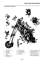
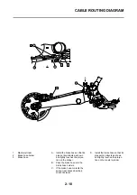
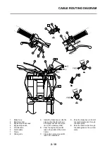
Brake hose
2.
Master cylinder
3.
Engine stop switch lead
4.
Engine stop switch
5.
Throttle cable
6.
Clutch cable
7.
Clamp
8.
Cable guide
A.
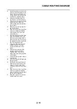
Install the brake hose so that its
pipe portion directs as shown
and lightly touches the projec-
tion on the master cylinder.
B.
Pass the engine stop switch
lead in the middle of the clutch
holder.
C.
Clamp the engine stop switch
lead to the handlebar.
D.
Pass the brake hose in front of
the number plate and through
the cable guide.
E.
Pass the clutch cable through
the cable guide on the number
plate.
(0 in)
0 mm
0 mm
(0 in)
Summary of Contents for YZ125 2015
Page 4: ......
Page 12: ...1 2 LOCATION OF IMPORTANT LABELS EUROPE...
Page 13: ...1 3 LOCATION OF IMPORTANT LABELS AUS NZ ZA...
Page 61: ...3 18 CHASSIS...
Page 165: ......
Page 166: ...PRINTED IN JAPAN E PRINTED ON RECYCLED PAPER...

