CABLE ROUTING
– 18 –
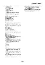
1. Rear wheel sensor lead
2. Brake hose (hydraulic unit to rear brake caliper)
3. Rear brake fluid reservoir hose
4. Seal
5. Brake hose (rear brake master cylinder to
hydraulic unit)
6. O
2
sensor lead
7. Rear brake light switch lead
8. Frame
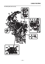
A. Route the rear wheel sensor lead to the outside of
the brake hose (hydraulic unit to rear brake
caliper). Make sure that the rear wheel sensor lead
is not twisted.
B. Align the holder with the pipe section of the brake
hose (hydraulic unit to rear brake caliper).
C. Position the holder halfway between the guide and
the end of the protective sleeve on the rear wheel
sensor lead as shown in the illustration.
D. Route the brake hoses to the inside of the frame.
E. To O
2
sensor
F. Fasten the seal to the frame with a plastic locking
tie. Face the buckle of the plastic locking tie inward
with the end pointing downward.
G. Position the end of the plastic locking tie to the
inside of the brake hoses.
H. Route the brake hoses on top of the frame.
I.
Point the end of the plastic locking tie rearward,
and then cut off the excess end of the tie to 5 mm
(0.20 in) or less.
J. Fasten the grommets on the rear wheel sensor
lead and the brake hose (hydraulic unit to rear
brake caliper) with the holder.
K. Fasten the rear wheel sensor lead and brake hose
(hydraulic unit to rear brake caliper) with the holder.
Route the rear wheel sensor lead over the brake
hose (hydraulic unit to rear brake caliper). Align the
holder with the pipe section of the brake hose
(hydraulic unit to rear brake caliper), making sure
that the white tape on the rear wheel sensor lead is
positioned to the front of the holder.
L. White tape
M. Route the rear brake light switch lead and O
2
sensor lead to the inside of the rear wheel
sensor lead.
N. Route the rear wheel sensor lead and brake hose
(hydraulic unit to rear brake caliper) through the
guide.
Summary of Contents for XSR700 2018
Page 1: ...2018 SUPPLEMENTARY SERVICE MANUAL XSR700 MTM690 MTM690 U BU3 F8197 E0...
Page 9: ...GENERAL SPECIFICATIONS 2 EAS20013 GENERAL SPECIFICATIONS Model Model BU31 MTM690 B9J1 MTM690 U...
Page 10: ...ELECTRICAL SPECIFICATIONS 3 EAS20016 ELECTRICAL SPECIFICATIONS Fuse Backup fuse 2 10 0 A...
Page 11: ...ELECTRICAL SPECIFICATIONS 4...
Page 47: ...FUEL TANK 40...
Page 63: ...SIGNALING SYSTEM 56...
Page 85: ...ABS ANTI LOCK BRAKE SYSTEM 78...
Page 89: ...ELECTRICAL COMPONENTS 82...
Page 91: ......
Page 92: ......


