CABLE ROUTING
– 14 –
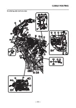
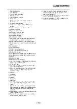
1. Rectifier/regulator
2. Headlight relay
3. Turn signal/hazard relay
4. Throttle cable
5. Radiator fan motor relay
6. Relay unit
7. Brake hose (front brake master cylinder to
hydraulic unit)
8. Front wheel sensor lead
9. Brake hose (hydraulic unit to left front brake
caliper)
10. Intake air temperature sensor coupler
11. ABS ECU coupler
12. Hydraulic unit assembly
13. ECU (Engine Control Unit)
14. Immobilizer unit coupler
15. Immobilizer unit lead
16. Wire harness (to ECU)
17. Sub-wire harness coupler (gear position switch,
coolant temperature sensor, fuel injector)
18. Brake pipe (hydraulic unit to rear brake caliper)
19. Brake pipe (rear brake master cylinder to hydraulic
unit)
20. Wire harness
21. Fuel pump coupler
22. Intake air pressure sensor
23. Intake air pressure sensor coupler
24. Main switch coupler
25. Handlebar switch coupler (right handlebar switch)
26. Handlebar switch coupler (left handlebar switch)
27. Frame
28. Main switch lead
29. Electrical components tray 1
A. Insert the projection on the bracket into the hole in
the sub-wire harness coupler.
B. White paint mark
C. Insert the projection on the wire harness holder
into the hole in the frame.
D. Route the handlebar switch lead (right handlebar
switch) over the handlebar switch lead (left
handlebar switch).
E. Upward
F. Outward
G. Downward
H. Inward
I.
Forward
J. Rearward
K. Insert the projection on the wire harness holder
into the hole in the frame from the bottom of the
frame.
L. Position the main switch leads, handlebar switch
lead (left handlebar switch), and handlebar switch
lead (right handlebar switch) as shown in the
illustration.
M. Face the buckle of the plastic band downward with
the end pointing inward.
N. Position the main switch couplers and handlebar
switch couplers under the frame.
O. Route the headlight relay lead and turn signal/
hazard relay lead through the rear hole in the
electrical component tray 1.
P. Insert the projection on the main switch lead holder
into the upper hole in the frame.
Q. Insert the projection on the wire harness holder
into the lower hole in the frame.
Summary of Contents for XSR700 2018
Page 1: ...2018 SUPPLEMENTARY SERVICE MANUAL XSR700 MTM690 MTM690 U BU3 F8197 E0...
Page 9: ...GENERAL SPECIFICATIONS 2 EAS20013 GENERAL SPECIFICATIONS Model Model BU31 MTM690 B9J1 MTM690 U...
Page 10: ...ELECTRICAL SPECIFICATIONS 3 EAS20016 ELECTRICAL SPECIFICATIONS Fuse Backup fuse 2 10 0 A...
Page 11: ...ELECTRICAL SPECIFICATIONS 4...
Page 47: ...FUEL TANK 40...
Page 63: ...SIGNALING SYSTEM 56...
Page 85: ...ABS ANTI LOCK BRAKE SYSTEM 78...
Page 89: ...ELECTRICAL COMPONENTS 82...
Page 91: ......
Page 92: ......


