


width. The valve seat will have removed
the bluing wherever it contacted the valve
face. Measure the seat width with vernier
calipers. It should measure approximately
1.3 mm. Also, the seat should be uniform
in contact area. If valve seat width varies,
or if pits still exist, then continue to cut
with the 45° cutter. Remove just enough
material to achieve a satisfactory seat.
Standard width Wear limit
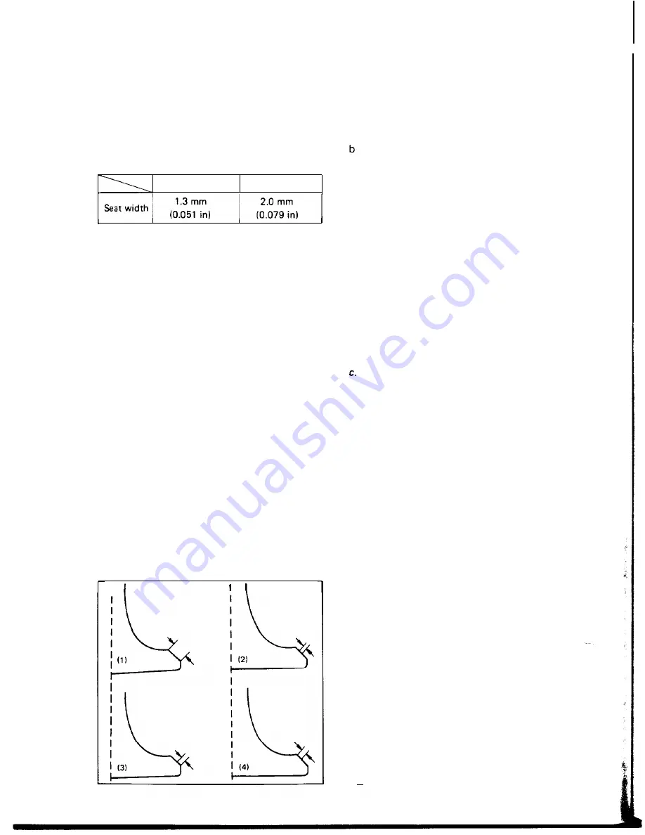
c. If the valve seat is uniform around the
perimeter of the valve face, but is too
wide or not centered on the valve face, it
must be altered. Use either the 8R, 45°
or 25° cutters to correct the improper
seat location in the manner described
below:
1)
2)
3)
4)
If the valve face shows that the valve
seat is centered on the valve face, but
too wide, then lightly use both the 8R
and the 25° cutters to reduce the seat
width to
1.3
m m .
If the seat shows to be in the middle
of the valve face, but too narrow, use
the 45° cutter until the width equals
1.3 mm.
If the seat is too narrow and right up
near the valve margin, then first use
the 8R cutter and then the 45° cutter
to get the correct seat width.
If the seat is too narrow and down
near the bottom edge of the valve
face, then first use the 25° cutter and
then the 45° cutter.
I
3. Lapping the valve/valve seat assembly.
a. The valve/valve seat assembly should be
Apply a small amount of coarse lapping
compound to valve face. Insert the valve
into the head. Rotate the valve until the
valve and valve seat are evenly polished.
Clean off the coarse compound, then
follow the same procedure with fine com-
pound.
Valve leakage check
Continue lapping until the valve face
shows a complete and smooth surface all
the way around. Clean off the compound
material. Apply bluing dye to the valve
face and rotate the valve face for full seat
contact which is indicated by a shiny sur-
face all around the valve face where the
bluing has been rubbed away.
lapped if
(1)
neither the seat nor the valve
face are severely worn, or (2) if the valve
face and valve seat have been resurfaced
and now require a final light grinding
operation for perfect sealing.
After all work has been performed on the
valve and valve seat, and all head parts
have been assembled, check for proper
valve/valve seat sealing by pouring solvent
into each of the intake ports, then the
exhaust ports. There should be no leakage
past the seat. If fluid leaks, disassemble
and continue to lap with fine lapping
compound. Clean all parts thoroughly,
reassemble and check again with solvent.
Repeat this procedure as often as neces-
sary to obtain a satisfactory seal.
D. Valve spring
1. Checking the valve springs
a. This engine uses two springs of different
sizes to prevent valve float or surging. The
c h a r t b e l o w s h o w s t h e b a s i c v a l u e
characteristics.
b. Even though the spring is constructed of
durable spring steel, it gradually loses
some of it’s tension. This is evidenced by
a gradual shortening of free length. Use a
vernier caliper to measure spring free
length. If the free length of any spring has
decreased more than 2 mm (0.08 in) from
its specification, replace it.
24
Summary of Contents for XS650SE
Page 1: ......
Page 4: ...CHAPTER 1 GENERAL INFORMATION l l MACHINE IDENTIFICATION a 1 l 2 SPECIAL TOOLS...
Page 39: ......
Page 45: ......
Page 55: ......
Page 76: ......
Page 77: ......
Page 78: ......
Page 79: ...XS650E Supplementary FOR XS650E MODELS AFTER ENGINE SERIAL NO 2FO 006501...
Page 84: ..._ _ _I __ l i _ _ I l R...
Page 108: ......
Page 109: ......
Page 110: ......
Page 111: ......
Page 112: ......
Page 116: ...MAINTENANCE AND LUBRICATION CHART PERIODIC MAINTENANCE EMISSION CONTROL SYSTEM 3...
Page 117: ...t c c...
Page 140: ......
Page 141: ...Supplementary...
Page 149: ...2 Troubleshooting inspection...
Page 150: ...LOW BEAM DOES NOT LlGHT WHEN HIGH BEAM IS DEFECTIVE...
Page 161: ......
Page 162: ......
Page 163: ......
Page 164: ......
Page 165: ...Supplementary FOR XS650SE MODELS AFTER ENGINE SERIAL NUMBER 2FO 114241...
Page 174: ...R W wire to 118...
Page 175: ...119...
Page 186: ......
Page 187: ......
Page 188: ......
Page 189: ......
Page 190: ......
Page 200: ...1...
Page 202: ...Torque Specifications A Nut...
Page 212: ......
Page 213: ......
Page 214: ......
Page 215: ......


