


QL5/QL1
137
5) – 9) Have the entire screen covered in white, red, green blue
and black each time (the example below shows the screen
in green) and check that there is no dot that is black or in
any other color.
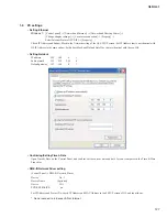
1-19. TOUCH PANEL Test
Contents Checks the input of the touch panel.
As the LCD is touched, the touch point scale appears
at the top and left of the LCD.
Also, at every touch of the LCD, the LCD luminance
changes between low and high.
After checking, select
[OK
] or
[NG]
as the check
result using the dialog box of the test program.
Example of executing screen
Input the check result using the dialog box as shown below.
LCD display
With the finished product, perform the following check
separately from this check. After initialization, turn on the
power by pressing the
B [SEL]
key, select [TOUCH SCREEN
CALIBRATION] from MENU, and press 4 corners of the
square sequentially. As a cross cursor appears, check that its
position is the same as the pressed position.
This check should be performed while sitting. If performed
while standing, the cursor will look to appear at slightly higher
position.
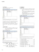
1-20. RECORDER Test
Contents: Checks the condition of the DataBUS and
AddressBUS by writing/reading the register of the
RECORDER IC (MP3 Decoder/Encoder).
C h e c k s t h e S I O c o n n e c t i o n w i t h D S P 7 b y
transmitting and receiving signals.
Also, checks the CPU connection between DSP7 and
SH7724 by transmitting and receiving signals.
Example of executing screen
Display in case the check result is NG
1) CPU Interface (Data Bus)....
NG: IC402 0000 XXXX 0000 0000 0000 X00X
←
X = Error bit
MSB
LSB
2) SIO Connection (DSP7
→
RECORDER)
NG: IC206 [SO08]
→
IC402 [BDR0]
SIO Connection (RECORDER
→
DSP7) ...
NG: IC402 [BDX0]
→
IC201 [SI09]
NG: IC402 [BDX0]
→
IC203 [SI09]
À
Summary of Contents for QL5
Page 5: ...5 QL5 QL1 QL5 QL1 19 828 4 272 563 Unit mm 468 272 562 19 DIMENSIONS...
Page 87: ...87 QL5 QL1 2NA WY63530 Scale 95 100 FX Circuit Board not installed Pattern side...
Page 90: ...QL5 QL1 90 B B DSP32 Circuit Board QL5 DSP16 Circuit Board QL1 2NA ZF60440...
Page 91: ...91 QL5 QL1 B B Scale 85 100 Pattern side 2NA ZF60440...
Page 92: ...QL5 QL1 92 HAAD Circuit Board C C 2NA ZH87070 1...
Page 94: ...QL5 QL1 94 HAAD Circuit Board D D 2NA ZH87070 1...
Page 95: ...95 QL5 QL1 D D Scale 58 100 Pattern side 2NA ZH87070 1...
Page 103: ...103 QL5 QL1 PNL PNCOM Circuit Board 2NA ZF60470 1 WR 31 0 1 Component side Pattern side...
Page 104: ...QL5 QL1 104 2NA ZF60450 1 PN16M Circuit Board PN16S Circuit Board QL5 F F...
Page 105: ...105 QL5 QL1 Component side 2NA ZF60450 1 Scale 90 100 F F...
Page 108: ...QL5 QL1 108 PNR PNCOM Circuit Board 2NA ZF60470 1 Component side...
Page 109: ...109 QL5 QL1 PNR PNCOM Circuit Board 2NA ZF60470 1 WR 31 0 1 WR 31 0 1 Pattern side...
Page 110: ...QL5 QL1 110 FD1M FDCOM Circuit Board FD2 FDCOM Circuit Board QL5 FD1M FD2 2NA ZK68030 H H...
Page 111: ...111 QL5 QL1 FD1M FD2 2NA ZK68030 H H Component side Scale 90 100...
Page 113: ...113 QL5 QL1 Pattern side Scale 90 100 not installed I I FD1M FD2 2NA ZK68030...
Page 114: ...QL5 QL1 114 Pattern side Component side FD1S FDCOM Circuit Board WR 6 1 2NA ZK68030...
Page 150: ...QL5 QL1 150 2 H 3 O X O 4 BOX 5x4 1 18 LCD Test LCD LCD 1 3 2 9 5 OK NG 1...
Page 169: ...QL5 QL1 169 5 Start QL OK Status Updating 1 1 6 OK Status Update Done 7 Status Error QL...
Page 173: ...QL5 QL1 173 CD CD Ctrl Audio CD wav OK 01 01 Ctrl P 8 8 8 8 m ON ON OVER 10 00 dB 0 00 dB...
Page 189: ...QL5 QL1 189 q w NG OK...
Page 191: ...QL5 QL1 191 y u i o F1 F12 0 Port Setting error Ethernet Network...


